Piezo crystal drive high speed switch valve

A technology of high-speed switching valves and piezoelectric crystals, applied in fluid pressure actuators, lifting valves, valve details, etc., can solve the problems of sensitive output displacement temperature changes, low output displacement, etc., and achieve high working pressure and load capacity Strong, high frequency response effect

Inactive Publication Date: 2009-09-02
ZHEJIANG UNIV
View PDF6 Cites 0 Cited by
  • Summary
  • Abstract
  • Description
  • Claims
  • Application Information

AI Technical Summary

Problems solved by technology

[0011] The purpose of the present invention is to provide a piezoelectric crystal-driven high-speed switching valve, which uses its high-frequency response and high output force characteristics to solve the contradiction between high-speed switching valve high-frequency response and high pressure and large flow, and at the same time overcome the piezoelectric crystal Low output displacement, output displacement is sensitive to temperature changes, etc.

Method used


Image

  • Piezo crystal drive high speed switch valve

Examples


Embodiment Construction

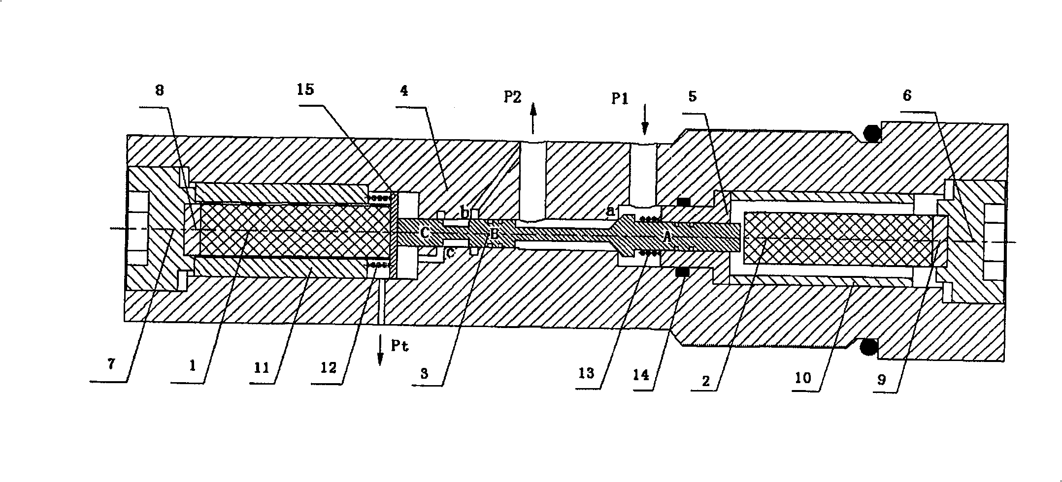
[0023] As shown in the accompanying drawings, the present invention is provided with a first driver casing 10 in one end hole of the valve body 4, and a first piezoelectric crystal 2 is housed in the first driver casing 10, and the first piezoelectric crystal 2 is close to an end of the outer side of the valve body 4. The first heat-shrinkable sheet 9 is installed, the first heat-shrinkable sheet 9 is embedded in the first end cover 6, and the valve sleeve 5 is installed in the hole of the valve body 4 at the other end of the first piezoelectric crystal 2; the hole at the other end of the valve body 4 A second driver jacket 10 is housed in the second driver jacket 10. A second piezoelectric crystal 1 is housed in the second driver jacket 1. A second heat shrinkable sheet 8 is installed on the end of the second piezoelectric crystal 1 near the outer side of the valve body 4. The second thermal Shrink sheet 8 is embedded in the second end cover 7, and the other end of the second ...


PUM


Abstract

The invention discloses a high-speed switching valve driven by a piezoelectric crystal. The piezoelectric crystals are respectively arranged at both ends of the valve body, and a cone valve-slide valve hybrid structure is installed in the valve body hole between the piezoelectric crystals, sliding in the hole of the valve sleeve inserted into the valve body and the hole of the valve body itself , and have a certain degree of valve port overlap, damping springs are set between the valve core and the valve sleeve, between the valve core and the baffle, and heat shrinkable sheets are embedded between the piezoelectric crystal and the selected end cap. Use the impact characteristics of the piezoelectric crystal actuator to solve the defect of small output displacement of the piezoelectric crystal; use the slide valve structure to enhance its load capacity and increase the movement stroke of the valve core; set a damping spring to reduce the vibration caused by the high-speed impact of the valve core; A temperature compensation sheet is added to solve the problem that the piezoelectric crystal is greatly affected by temperature. Realize a high-speed switching valve that can meet the requirements of high speed, high pressure and large flow at the same time.

Description

technical field [0001] The invention relates to an electro-hydraulic conversion control element, in particular to a high-speed switching valve driven by a piezoelectric crystal. Background technique [0002] As a new type of digital electro-hydraulic conversion control element, the high-speed switching valve adopts the pulse flow control method to realize high-precision pressure and flow control. It has the advantages of small size, high reliability, anti-pollution and simple structure, and has a wide application prospect. and development potential. The digital valve achieves micro control by increasing the response frequency, and the higher the frequency response, the higher the control accuracy. [0003] At present, there is a contradiction between high-speed response, high pressure and large flow in high-speed switching valves. Because the current high-speed switch valve driver is mainly a powerful electromagnet, the general response time is a few milliseconds, increasi...

Claims


Application Information

Patent Timeline
Patent Type & Authority Patents(China)
IPC IPC(8): F16K1/36F16K31/02F15B13/02
Inventor 欧阳小平蒋昊宜杨华勇
Owner ZHEJIANG UNIV
Why Eureka
Try Eureka