
Laser cutting device

A cutting device and laser technology, applied in auxiliary devices, welding/cutting auxiliary equipment, laser welding equipment, etc., can solve problems such as substrate deformation, adjustment of laser spot size and shape, and inability to remove coolant.

Inactive Publication Date: 2009-08-26
FOXSEMICON INTEGRATED TECHNOLOGY (SHANGHAI) INC +1
View PDF4 Cites 0 Cited by
  • Summary
  • Abstract
  • Description
  • Claims
  • Application Information

AI Technical Summary

Problems solved by technology

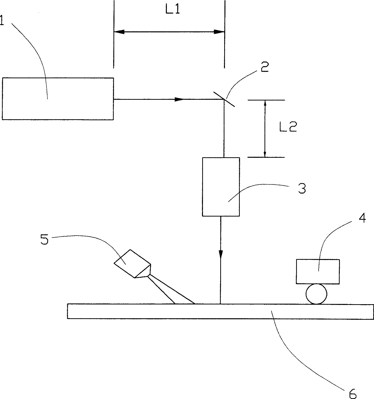
L1 and L2 are fixed distances. The optical components used in this optical path design are simple. However, when the size of the substrate 6 changes, the optical path system of the traditional laser cutting device cannot adjust the size and shape of the laser spot according to the change of the substrate. Meet the needs of cutting characteristics
[0007] In addition, the traditional pre-cutting tool 4 mostly uses a pneumatic cylinder to directly drive the cutting tool. When the tool cuts the substrate, it will be affected by the flatness of the substrate and cause uneven cutting depth.
Due to the compressibility of the gas itself and the hysteresis in force control, the tool driven by the pneumatic cylinder responds poorly to the flatness of the substrate surface, resulting in uneven cutting depth
[0008] Moreover, the suction force of the traditional metal vacuum chuck is affected by the position of the vacuum source, and the suction force on the substrate cannot be very uniform, so that the substrate is easily deformed due to uneven suction force, so that the cutting depth of the substrate is uneven
In addition, the traditional metal vacuum chuck cannot quickly and effectively remove the excess coolant during the cutting process

Method used


Image

  • Laser cutting device
  • Laser cutting device
  • Laser cutting device

Examples


Embodiment Construction

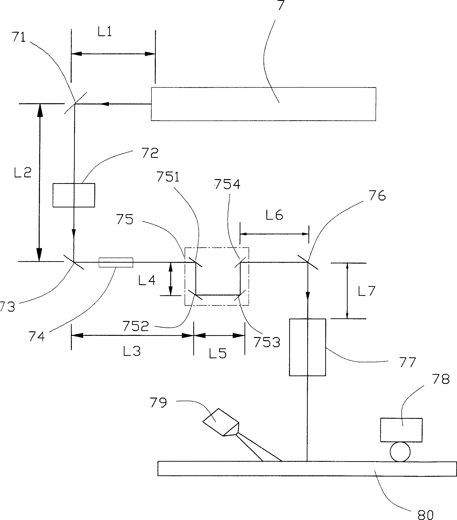
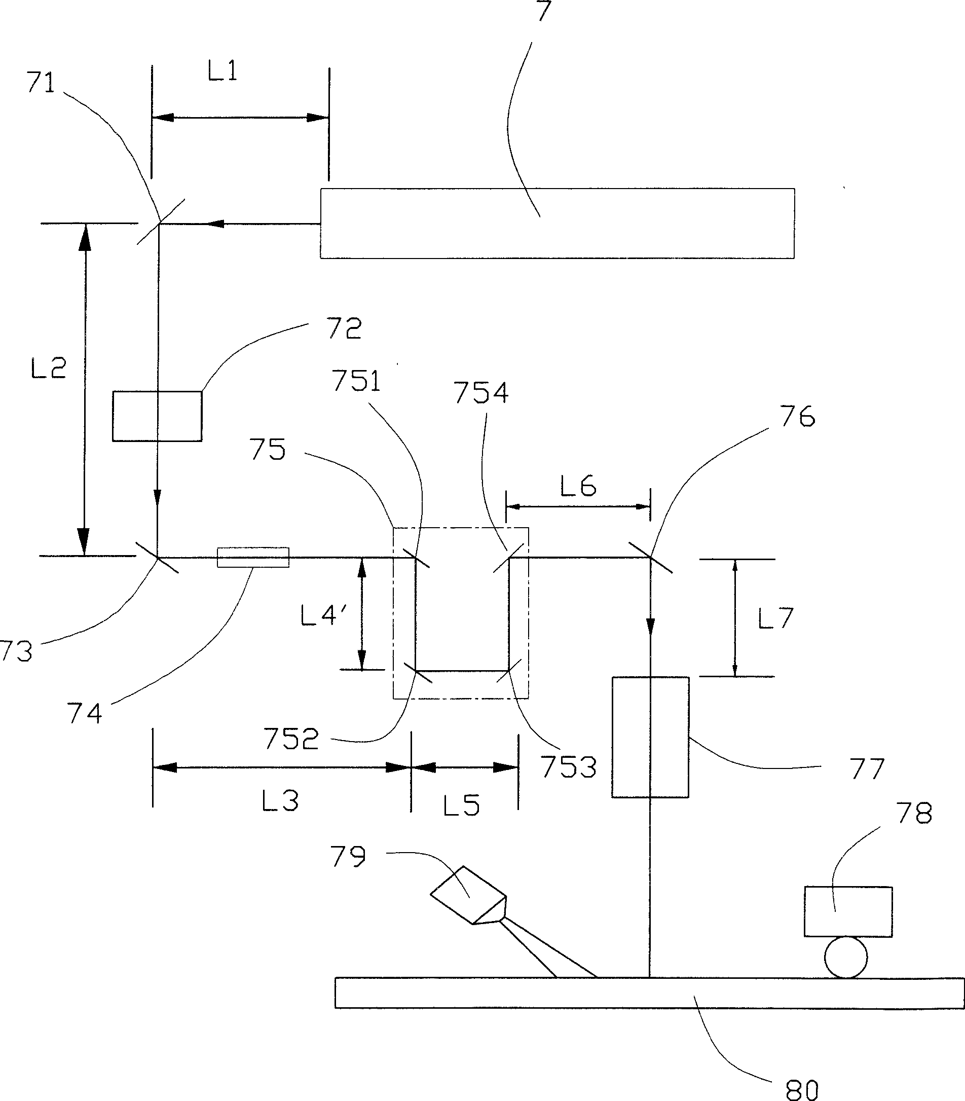
[0021] Such as figure 2 and image 3 As shown, the laser cutting device of the present invention is used for cutting brittle substrates (not shown), which includes a pre-cutting system 78 , a laser light system and a cooling system 79 . Above-mentioned laser optical system comprises the laser cavity 7 for producing laser light, the first reflection mirror 71, photointerrupter 72, the second reflection mirror 73, collimator (Collimator) 74, optical distance adjustment system 75, the first Three reflective mirrors 76 and a focusing lens group 77 . The laser cavity 7 generates laser light, and in the present invention, the laser light is carbon dioxide laser light. After the laser light is emitted from the laser cavity 7, it is reflected by the first reflector 71 and passes through the photointerrupter 72 to the second reflector 73, and after being reflected by the second reflector 73 and entering the collimator 74, the laser light becomes a parallel beam. Then the laser ligh...


PUM


Abstract

A laser-cutting device for cutting brittle basilar plates includes pre-cutting systems, laser optical system and cooling system, said pre-cutting system is used for forming pre-cutting line on the basilar plates; said laser optical system is used for producing laser light, and the laser light heats the basilar plates along the pre-cutting line to making the basilar plates thermal expansion; said cooling system is used for cooling said thermal expanding basilar plates; said laser optical system includes laser cavity generating said laser light and optical path adjustment system, the optical path adjustment system is equipped on the optical path on the basilar plates and illuminated by said laser light to adjusting the length of the optical path, so it can adjust the size of laser light point to meet different cutting needs.

Description

【Technical field】 [0001] The present invention discloses a laser cutting device, in particular to a laser cutting device for cutting brittle materials such as liquid crystal display (TFT-LCD) (Thin Film Transistor, TFT for short; Liquid Crysta Display, LCD for short) glass panel . 【Background technique】 [0002] With the continuous development of display technology, liquid crystal display devices (TFT-LCD) have been widely used in consumer fields due to their own characteristics. It is regarded as a strong opponent to replace the traditional cathode ray tube (Cathode Ray Tube, CRT for short) display device. [0003] A liquid crystal display device is generally composed of two glass substrates, liquid crystal contained in the two glass substrates and a number of circuits. The liquid crystal can change the arrangement mode under the influence of the electric field to complete the display operation. In order to form liquid crystal display panels of different sizes, it is gen...

Claims


Application Information

Patent Timeline
Patent Type & Authority Patents(China)
IPC IPC(8): B23K26/04B23K26/06B23K26/42B23K37/04
Inventor 傅承祖黄俊凯陈献堂张明辉许宗富郭访璇
Owner FOXSEMICON INTEGRATED TECHNOLOGY (SHANGHAI) INC
Learn More