Connector

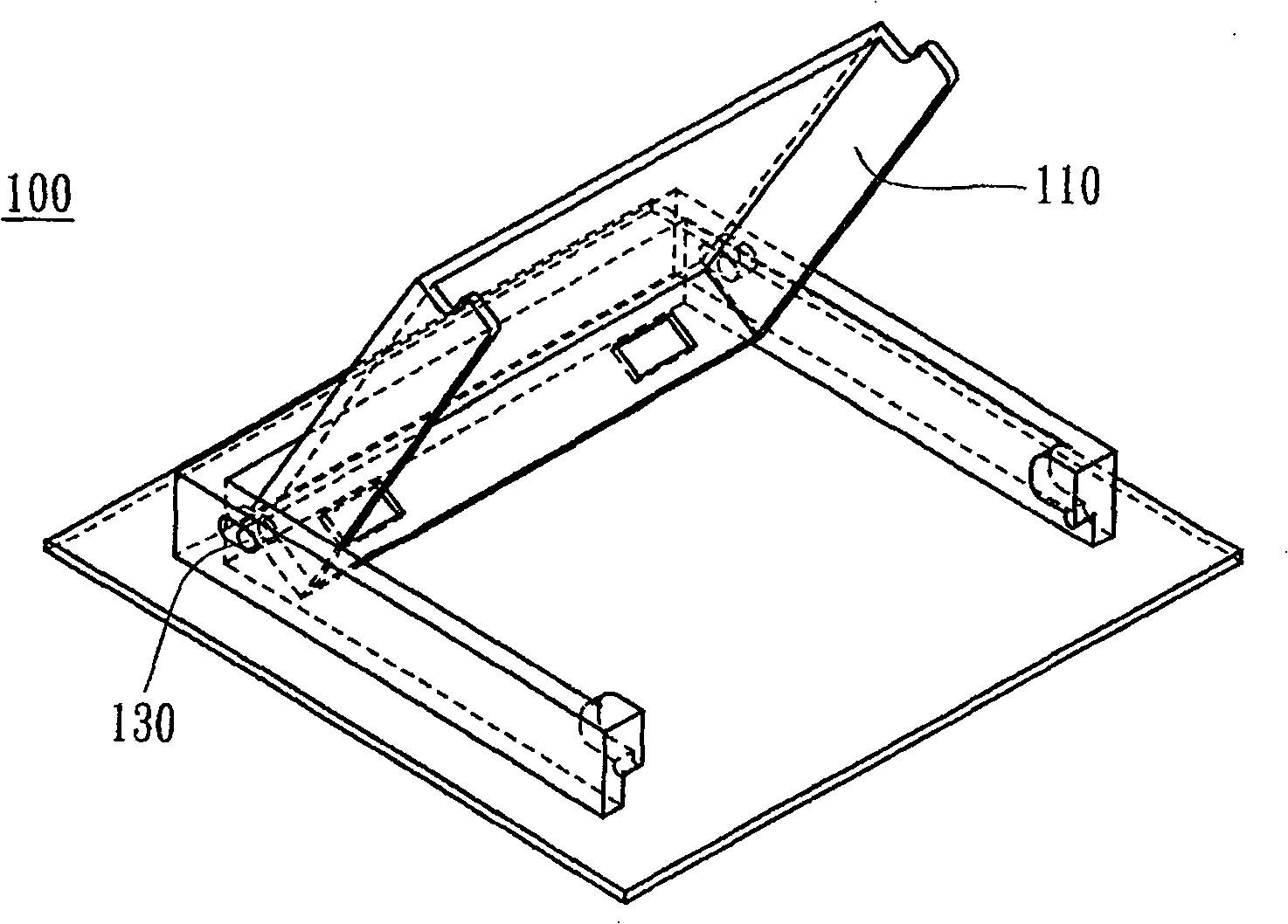
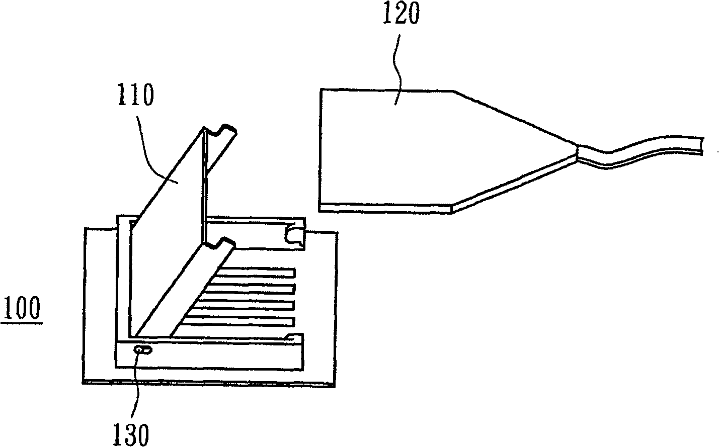
A connector and contact terminal technology, which is applied in the direction of connection, electrical components, base/casing, etc., can solve the problems such as the space occupied by the upper cover, the increase in product cost, and the damage of the protection cover rotating mechanism 130, so as to reduce the cost and improve the service life. Effect

Active Publication Date: 2009-08-19
AU OPTRONICS CORP
View PDF6 Cites 0 Cited by
  • Summary
  • Abstract
  • Description
  • Claims
  • Application Information

AI Technical Summary

Problems solved by technology

The design of this type of connector mechanism not only requires a relatively large number of operating steps, but the upper cover obviously takes up a lot of space. For devices that continue to be miniaturized, it is no different from adding troubles to assembly.
Moreover, when the protective upper cover is rotated and opened and closed too frequently, or when the user operates incorrectly, it is easy to cause damage to the protective upper cover 110 or the rotating mechanism 130 of the connector.
More particularly, when the protective upper cover of this type of connector is damaged, it is usually difficult to repair or replace only the part of the protective upper cover, but the connector must be replaced as a whole, which will inevitably lead to an increase in product cost

Method used


Image

  • Connector
  • Connector
  • Connector

Examples


Embodiment Construction

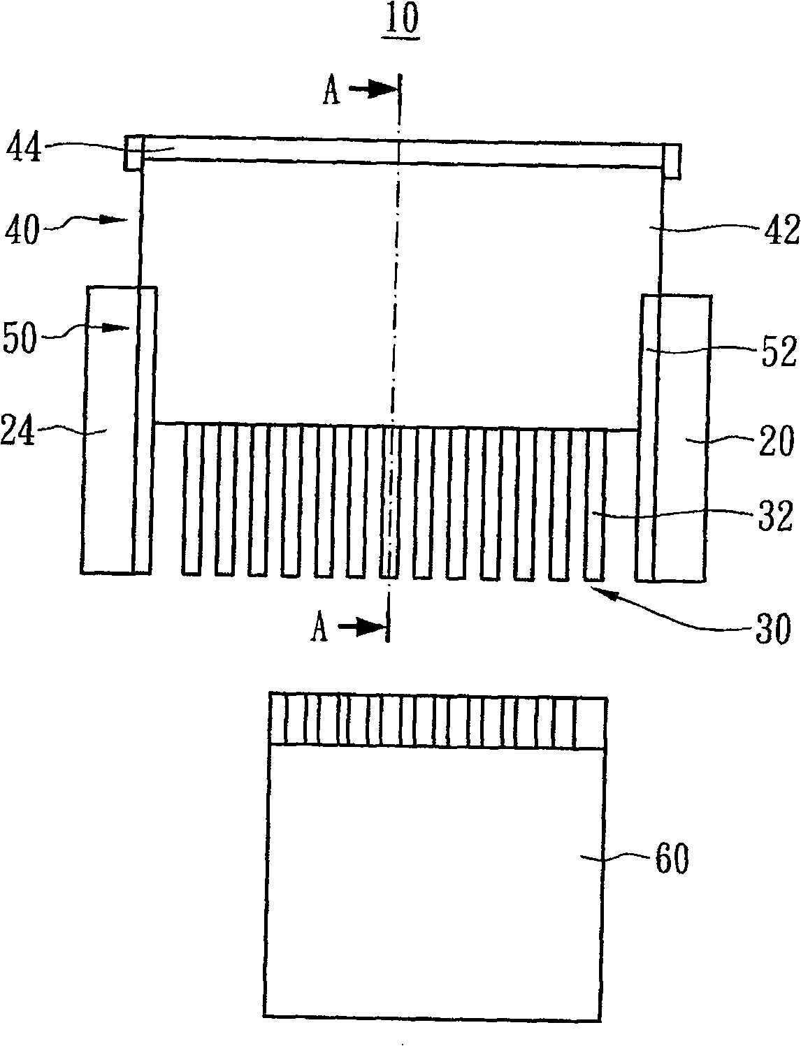
[0026] Please refer to Figure 2A and Figure 2B ,in Figure 2A shows a top view of an embodiment of the connector of the present invention, and Figure 2B shown as Figure 2A Sectional view along line A-A'. The connector of the present invention can be widely applied to various current printed circuit boards. The size and shape of the connector shown in the drawings of the present invention are only used to help explain the present invention, not to limit the present invention.

[0027] According to an embodiment of the present invention, the connector 10 includes a base 20 , at least one first terminal 30 , an upper cover 40 and a sliding structure 50 . The connector 10 can be electrically connected to a signal line 60 , wherein the signal line 60 can be a flexible printed circuit (FPC) or similar signal line. Specifically, the base 20 includes a body 22 and two opposite side portions 24 respectively located at two ends of the body, wherein the body 22 provides a platfo...


PUM


Abstract

This is a commutator includes a base, at least one premier terminals, one top cover and a sliding structure. The base is of two side definite a space. The premier terminal includes a contacting end and a fixing end, with the former one in the space and the later one out of the space. The sliding structure is fixed to the two sides of the base and facing to the two sides of the top cover allowing it slide on it.

Description

technical field [0001] The invention relates to a connector; in particular to a connector with a sliding upper cover. Background technique [0002] In current electronic products, signal lines are commonly used to connect multiple printed circuit boards (PCBs) for various signal transmission purposes, and common signal lines are flexible flat cables. The terminal is a terminal composed of a plurality of pins. Correspondingly, a connector is provided on the printed circuit board for insertion of signal lines. Since these connectors are also provided with a plurality of pins inside, which can respectively correspond to the pins of the signal line terminals, when the signal line is inserted into the connector, the purpose of signal transmission can be achieved. [0003] Please refer to Figure 1A and Figure 1B , the existing connector 100 is a clamshell type, that is, it has a protective cover 110 similar to a piano keyboard cover. When using this clamshell connector, it i...

Claims


Application Information

Patent Timeline
Patent Type & Authority Patents(China)
IPC IPC(8): H01R12/24H01R12/28H01R13/46H01R12/79
Inventor 王琳
Owner AU OPTRONICS CORP
Why Eureka
Try Eureka