
Optical imaging system for helmet display

An optical imaging system and head-mounted display technology, applied in optics, optical components, instruments, etc., can solve the problems of not being fully reflected, image distortion, image blur, etc., to improve the utilization rate of light energy, reduce image distortion, The effect of correcting edge aberrations

Inactive Publication Date: 2009-08-12
深圳市合力泰光电有限公司
View PDF4 Cites 0 Cited by
  • Summary
  • Abstract
  • Description
  • Claims
  • Application Information

AI Technical Summary

Problems solved by technology

[0005] Compared with the original technology, this design can greatly improve the utilization rate of light energy, but due to the introduction of another reflective surface 11, in fact, it cannot be completely reflected, and part of the light energy will be lost in the process of reflection
Moreover, due to the many optical surfaces passing through, the image is prone to adverse consequences such as imaging distortion and aberration, and the technical requirements have also been improved a lot, and the current situation of image blur has not been improved. still feel tired

Method used


Image

  • Optical imaging system for helmet display
  • Optical imaging system for helmet display
  • Optical imaging system for helmet display

Examples


specific Embodiment 1

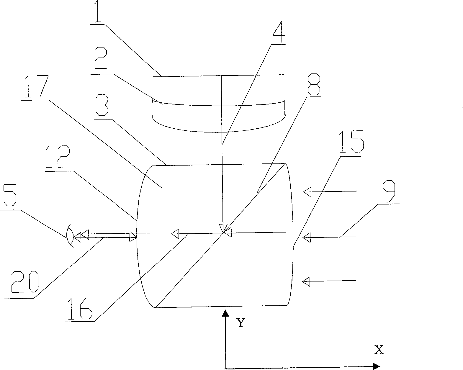
[0027] Specific embodiment one, such as image 3 As shown, from the first direction according to the incident direction of the first ray 4 are the image information display source, the free-form surface prism 2 and the combined prism 17, and from the second direction according to the incident direction of the second light 9 are the combined prism 17 and the eyepiece 12. The image information display source is preferably a miniature liquid crystal display 1, and can also be other displays such as OLED or PDP that can display images. The optical axis of 2 is coaxial with the optical axis in the vertical direction of the combined prism 17, and the optical axis of the eyepiece 12 is coaxial with the optical axis in the horizontal direction of the combined prism 17, so as to ensure that the light will not be generated due to the difference in the optical axis during the propagation process. Aberration distortion. Half mirror 8 is positioned in combined prism 17, and is positioned...

specific Embodiment 2

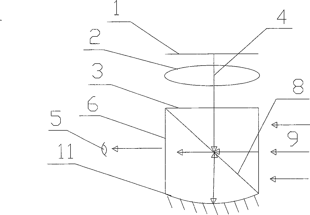
[0030] Specific embodiment two, different from specific embodiment one is that the mirror surface of eyepiece 12 facing the human eye is a convex surface, this convex surface is located on the optical path of the third light ray 16, has the effect of divergence, and the focus of the eyepiece is that the light passes through the free-form surface prism and The converging point after the semi-reflective mirror is emitted, the light emitted through the eyepiece becomes parallel light, which reaches the human eye directly.

specific Embodiment 3

[0031] Specific embodiment three, different from specific embodiments one and two is that the combined prism has a convex surface 15 on the side close to the outside world, and the convex surface 15 is located on the optical path of the second light 9, so that the second light 9 enters the combined prism 17 After converging, its optical path coincides with the optical path of the first light 4 emitted by the miniature liquid crystal display 1 on the half mirror 8 . The curvature of the convex surface 15 is calculated to ensure that the light passing through the transflective optical surface can coincide with the light emitted by the liquid crystal display and reflected by the transflective optical surface to ensure image quality.


PUM


Abstract

The invention discloses an optical imaging system for a head-mounted display, comprising an image information display source, a free-form surface prism and a combination prism, the first light (4) emitted by the image information display source enters the combination prism through the free-form surface prism, and at least one of the combination prisms Contains a half mirror positioned on the optical path of a first ray (4) incident on it from a first direction and positioned on a second ray incident from outside on it from a second direction On the light path of (9), the first ray (4) after being reflected by the half-mirror and the second ray (9) transmitted through the half-mirror surface synthesize the third ray (16) and then enter the viewer pupil. The invention improves the utilization rate of light energy and reduces imaging distortion and aberration.

Description

【Technical field】 [0001] The invention relates to a head-mounted display, in particular to an optical imaging system of the head-mounted display capable of adjusting focus, improving optical utilization, and reducing imaging distortion and aberration. 【Background technique】 [0002] Head Mounted Display (HMD) is referred to as HMD, which can amplify the image generated by the small two-dimensional display through the optical system, into a screen effect of tens of inches away from several feet. It is mainly composed of: image information display system, optical imaging system, circuit control and connection system, helmet structure and weight system, audio system, etc. Among these five parts, the optical imaging system is the most critical, because the user observes the image through the optical imaging system. If the design is not reasonable, the image will have problems such as imaging distortion, insufficient brightness, etc., and the user will feel sick or the eyes will ...

Claims


Application Information

Patent Timeline
Patent Type & Authority Patents(China)
IPC IPC(8): G02B27/00
Inventor 何志奇陈学刚陈超伟
Owner 深圳市合力泰光电有限公司
Learn More