Connector device for card

A card connector, installation and positioning technology, applied to the parts of the connection device, the device for preventing wrong connection, connection, etc., can solve the problem of unstable contact, buckling of the contact 52, difficulty in miniaturization of the connector device, etc. problems, to achieve the effect of improving contact reliability, preventing buckling or deformation, and easy contact reliability

Inactive Publication Date: 2009-05-27
ALPS ALPINE CO LTD
View PDF5 Cites 0 Cited by
  • Summary
  • Abstract
  • Description
  • Claims
  • Application Information

AI Technical Summary

Problems solved by technology

[0012] However, in the structure of the conventional card connector device, the contact (connector terminal) 52 held on the insulator (housing) 51 is inserted into the card 20 by forming the free end side of the contact 52a. direction from the inside to the front (card insertion slot direction), so there is a problem that, for some reason, the contact 52a is mounted to the lower side of the card housing portion, When the card 20 is inserted, the front end of the card 20 will collide with the front end of the contact 52a, which will cause the contact 52 to buckle or deform, resulting in poor contact.
[0013] In addition, in order to prevent the front end of the contact 52a from colliding with the front end of the card 20, and to bend it upward and protrude in advance, it is necessary to set the height of the insulator high so as not to touch the contact when the card 20 is inserted. The point 52a protrudes from the insulator (housing) 51, so there is another problem of increasing the size of the connector device
[0014] In addition, as long as the contact (connector terminal) 52 held on the insulator (housing) 51 is formed in such a manner that the free end side forming the contact 52a extends inward with respect to the insertion direction of the card 20, But in this case, just become the form that the holding part of contact 52 is oppositely positioned at the insertion port side of card accommodating part, so when card is inserted, when contact 52a of contact 52 contacts with card, as insulator The card insertion port side on the free end side of 51 will be bent toward the card receiving part side due to the elastic pressure of the contact 52, and the contact pressure with the card cannot be ensured.
[0015] In addition, in the structure of the conventional card connector device, the contact portion of the detection switch that detects the insertion state of the card is formed by a contact spring that rotates around the pivot point, and the contact spring is obtained by the same contact spring. The self-restoration of the point spring uses the elastic pressure and the contact pressure of the contact part. Therefore, after a long period of use, there will be problems such as the contact spring slack and falling down, the contact pressure drops, and the contact is unstable.
In addition, in order to increase the contact pressure, the contact spring must be enlarged, so the housing must be enlarged, so there is a problem that it is difficult to realize the miniaturization of the connector device.

Method used


Image

  • Connector device for card
  • Connector device for card
  • Connector device for card

Examples


Embodiment Construction

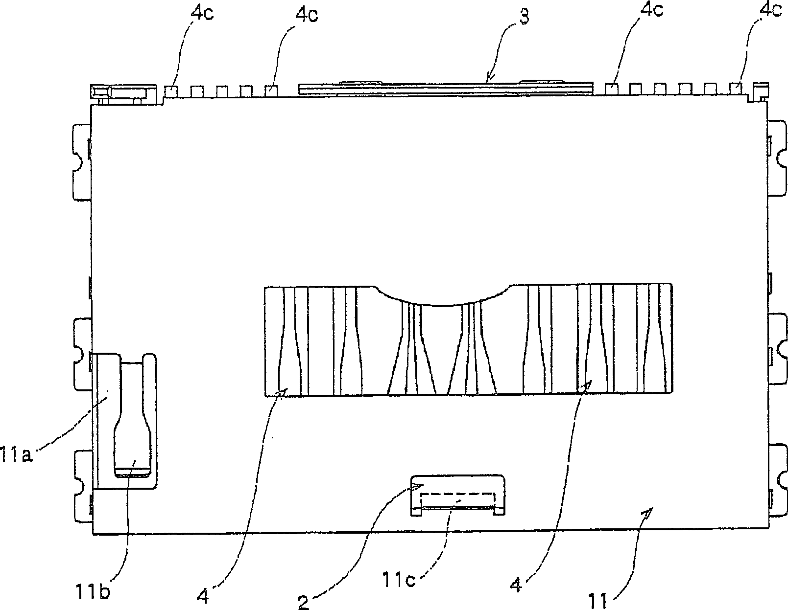
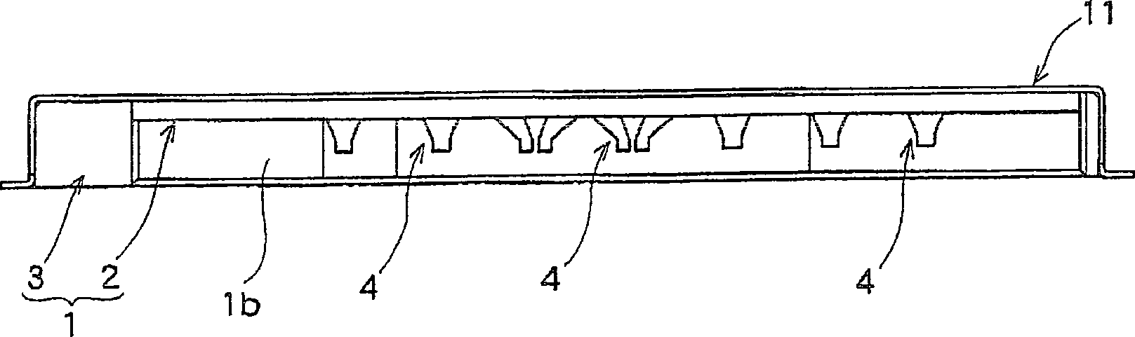
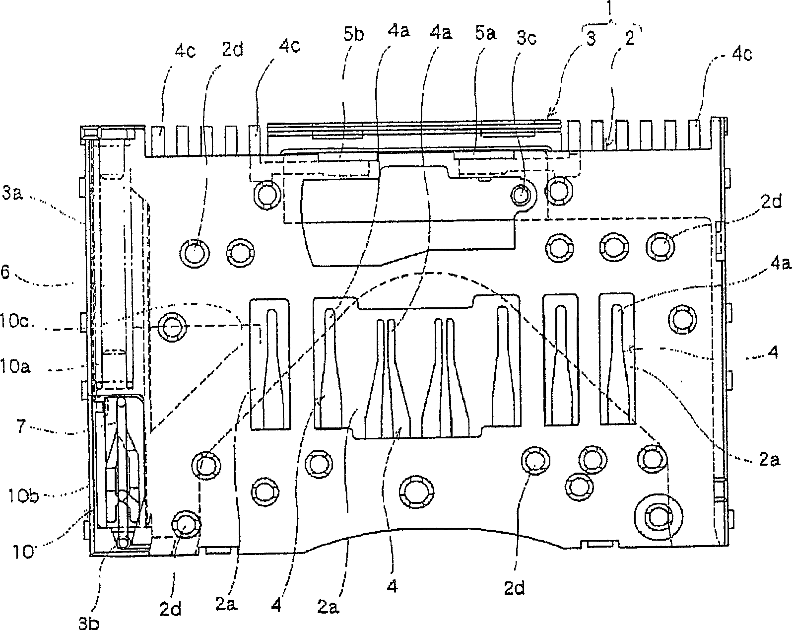
[0065] Hereinafter, embodiments of the present invention are shown in Figure 1 to Figure 15 middle. figure 1 is a top view of the card connector device, figure 2 is the front view of the card connector unit, image 3 It is a plan view of the card connector device in a state where the cover member is removed, Figure 4 is a sectional view of the main part of the card connector unit, Figure 5 It is a plan view of the card connector device at the card ejection position, and Fig. 6 is a sectional view of the main part of the card connector device at the card ejection position, Figure 7 It is a plan view of the card connector device in the middle of card insertion, Figure 8 It is a cross-sectional view of the main part of the card connector device in the middle of card insertion, Figure 9 is a plan view of the card connector device at the card insertion position, Figure 10 is a sectional view of the main part of the card connector device at the card insertion position, ...


PUM


Abstract

PROBLEM TO BE SOLVED: To provide a connector device for a card capable of preventing contact parts of contact terminals from buckling or deforming at insertion of the card, with contact reliability of the contact parts improved, and downsizing of the device. ŽSOLUTION: The connector device is provided with a housing 1 with connector terminals 4 arranged, and the connector 4c led out of the connector terminals and protruded toward outside of the housing 1, of which, the housing 1 is composed of an upper case 2 and a lower case 3, and the connector terminals 4 have their one end extended rearward from a card insertion side of the upper case 2, with the contact parts 4a formed in bending into a storage part 1a through window hole parts 2a provided at the upper case 2, and their other end extended to a rear part of the upper case along both side edges of the window hole parts 2a of the upper case 2 to form the connector 4c in protrusion outward from the housing 1. Ž

Description

[0001] This application is a divisional application, the application number of its parent application: 2004100865915, the application date: 2004.10.19, the name of the invention: card connector device technical field [0002] The present invention relates to the structure of a card connector device used for small memory cards and the like used in various portable information terminals such as mobile phones and PCs, digital cameras, digital AV equipment and other memory-applied devices. Background technique [0003] As an additional storage device for electronic equipment such as a personal computer or a digital camera, a card connector device is generally used. As a storage medium of this card connector device, a PC card, a memory card, etc. are widely used. As this conventional card connector device, there is known one in which a housing portion for inserting a card is formed inside a casing such as a casing, and a plurality of connector terminals (contacts) are arranged in...

Claims


Application Information

Patent Timeline
Patent Type & Authority Patents(China)
IPC IPC(8): H01R13/641H01R13/71H01R12/16G06K17/00H01R13/64
Inventor 山田裕树川端隆志加贺谷浩之
Owner ALPS ALPINE CO LTD
Why Eureka
Try Eureka