Light-source drive circuit, Luminescence device and balanced transformer with current feedback

A light source driving circuit and light emitting device technology, which is applied in the direction of electric lamp circuit layout, light source, electric light source, etc., can solve the problem of no feedback lamp current and so on

Active Publication Date: 2009-05-20
AU OPTRONICS CORP
View PDF6 Cites 0 Cited by
  • Summary
  • Abstract
  • Description
  • Claims
  • Application Information

AI Technical Summary

Problems solved by technology

Similarly, in this patent, there is no ability to feed back the lamp current, just like the problem in US6534934 B1 patent

Method used


Image

  • Light-source drive circuit, Luminescence device and balanced transformer with current feedback
  • Light-source drive circuit, Luminescence device and balanced transformer with current feedback
  • Light-source drive circuit, Luminescence device and balanced transformer with current feedback

Examples


Embodiment Construction

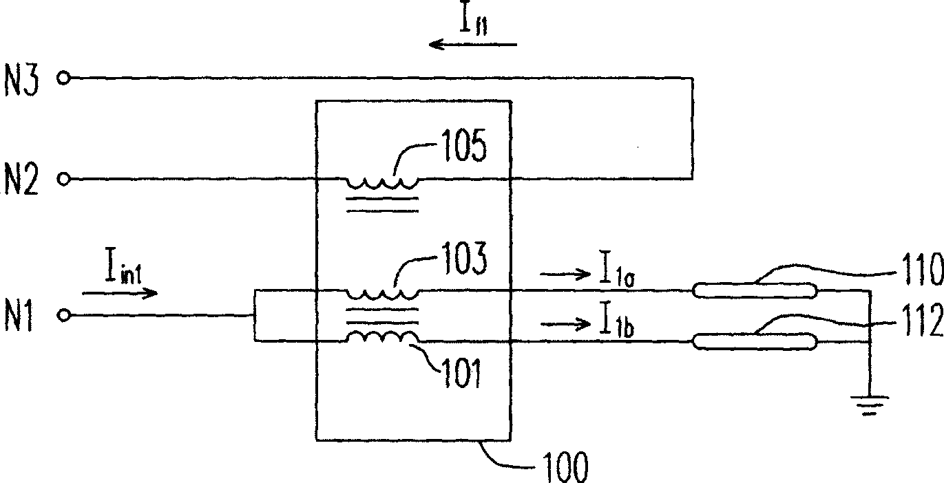
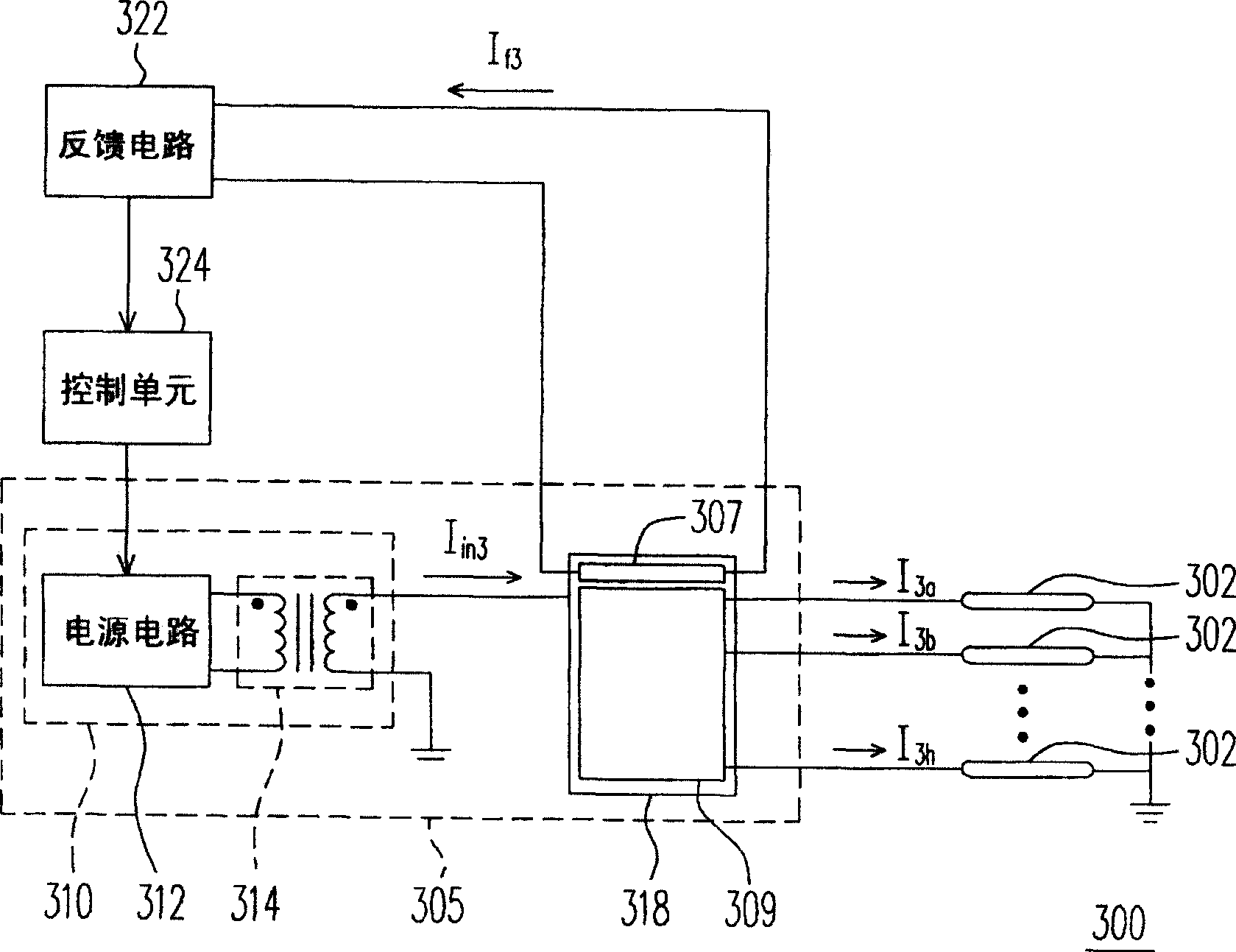
[0056] figure 1 It is a circuit diagram of a driving circuit with feedback control according to a preferred embodiment of the present invention. Please refer to figure 1 , the driving circuit provided in this embodiment includes a balanced transformer 100 . The balanced transformer 100 can be based on the driving signal I in1 to synchronously drive multiple loads, such as loads 110 and 112. In this embodiment, the drive signal I in1 For example, it is in the form of current, which can be converted by a power conversion circuit (such as image 3 314) generated.

[0057] The balanced transformer 100 includes coils 101, 103 and 105, especially, the three coils have a common core structure for generating a load current I 1a and I 1b to drive the loads 110 and 112. One end of the coil 101 and the coil 103 are coupled to a common node N1, and the other ends are respectively coupled to loads 110 and 112 . It should be noted that the number of turns of the coil 101 , the coil...


PUM


Abstract

The invention provides a light source driving circuit, a lighting device with current feedback and a balance transformer, where the lighting device comprises multiple light sources, power supply converting circuit, multiple load driving coils and feedback generating coil, where the power supply converting circuit generates drive signal to the load driving coils to generate the same drive current to drive each light source. Besides, the feedback generating coil induces the currents flowing through the load driving coils to generate feedback signal. And the invention can make the brightness of the light source reach the ideal set value.

Description

technical field [0001] The present invention relates to a lighting device, and in particular to a lighting device with a feedback function. Background technique [0002] Now is a 3C era, that is, the era of Computer, Communication and Consumer electronics. In this kind of life, there are many kinds of information devices on the market, such as digital tools such as mobile phones, digital cameras, digital video cameras, notebook computers, and desktop computers, all of which are developing in a more convenient, multi-functional and beautiful direction. [0003] In most of the information devices, the flat-panel display is used as the main communication interface. Through the display function of the flat-panel display, users can operate the product more conveniently. Liquid crystal displays have gradually replaced cathode ray tube displays and become the mainstream of the market due to their superior characteristics such as power saving, high image quality, high space utiliza...

Claims


Application Information

Patent Timeline
Patent Type & Authority Patents(China)
IPC IPC(8): G09G3/18G09G3/36H05B37/02
Inventor 孙嘉宏李宗勋陈幸茹廖振能
Owner AU OPTRONICS CORP
Why Eureka
Try Eureka