
Full optical fiber optical optical tweezers system

An all-fiber, optical tweezers technology, applied in the field of optical tweezers systems, can solve the problems of many optical devices, complex device coupling and connection, lack of flexibility, etc., to achieve the effect of simple coupling and connection, easy configuration and use, and enhanced reliability

Inactive Publication Date: 2009-04-29
QUANTUMLINK TECH
View PDF3 Cites 1 Cited by
  • Summary
  • Abstract
  • Description
  • Claims
  • Application Information

AI Technical Summary

Problems solved by technology

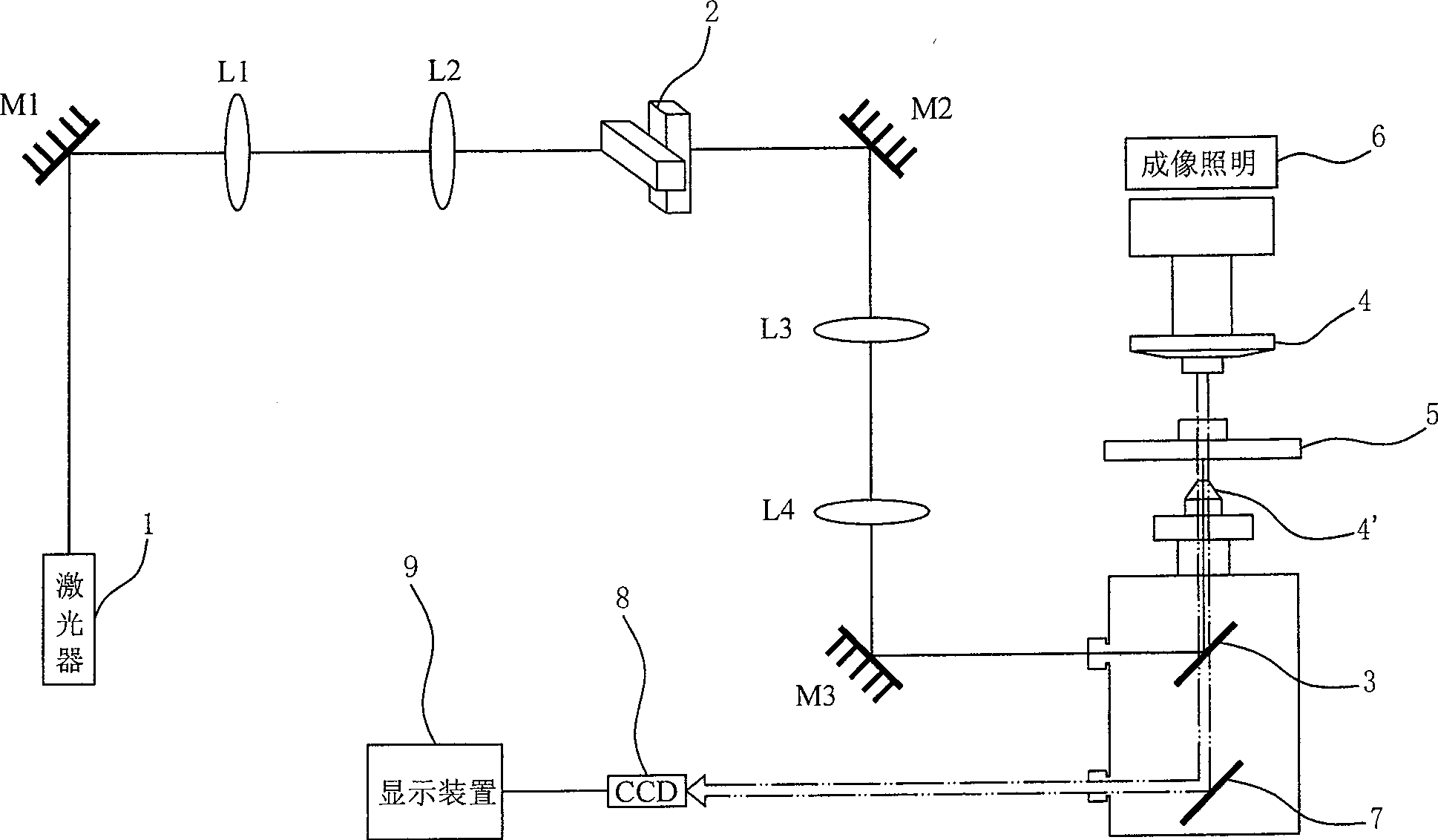
[0004] The technology related to the microscope-based optical tweezers system has matured, but there are still inherent disadvantages in its structure, mainly as follows: the optical tweezers system uses many optical devices, resulting in relatively difficult coupling and connection between devices. Complicated, precise adjustment and collimation adjustment are more difficult, thereby reducing the reliability of the system, and the operation and maintenance of the system are more troublesome; the optical microscope is used as the main body of the optical tweezers system, which must occupy a light inlet of the optical microscope, which affects the microscope. The provision of light sources and lack of structural flexibility for research areas that require multiple manipulation functions

Method used


Image

  • Full optical fiber optical optical tweezers system
  • Full optical fiber optical optical tweezers system
  • Full optical fiber optical optical tweezers system

Examples


Embodiment Construction

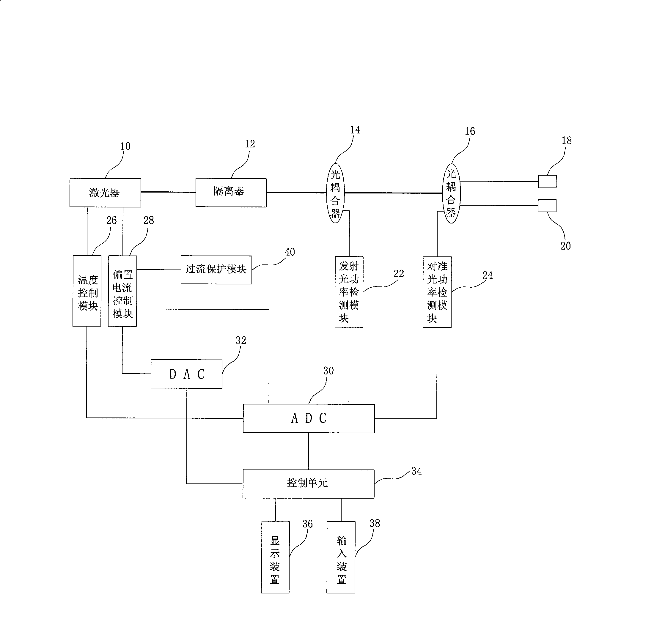
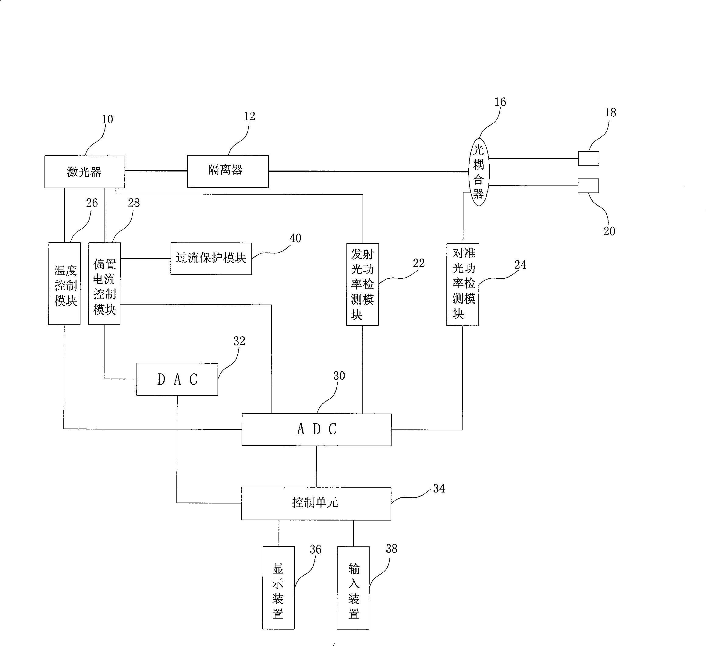
[0021] refer to figure 2As shown, it is a schematic structural view of the all-fiber optical tweezers system of the present invention, which includes a laser 10, an isolator 12, a first optical coupler 14, a second optical coupler 16, an optical fiber connector 18 / 20, and an emission optical power detection Module 22, alignment optical power detection module 24, temperature control module 26, bias current control module 28, analog-to-digital converter 30, digital-to-analog converter 32, control unit 34, display device 36, input device 38 and overcurrent protection Module 40, wherein the laser 10 is a high-power light-emitting diode laser with a pigtail. The isolator 12 is connected with the optical fiber of the laser 10, which allows the polarized light to pass in one direction. Therefore, after the beam emitted by the laser 10 is output to the isolator 12, the isolator 12 only allows the beam to pass in one direction, so that the beam will not be reflected back. Laser 10, s...


PUM


Abstract

The present invention discloses an all-fiber tweezers system, connected at least by a laser, a first optical coupler, a second optical coupler, two fiber connectors, an emission power detecting module, a bias control module, an analog-to-digital converter, a digital-to-analog converter, and a control unit, wherein all optical devices are all-fiber devices, which is easier for coupling and connecting the optical devices and for integrating the system, and at the same time the reliability of the system is improved. Besides, the all-fiber tweezers system does not occupy the light portal of the microscope, thereby being convenient for researchers to allocate and utilize.

Description

【Technical field】 [0001] The invention relates to a control device utilizing optical means, in particular to an optical tweezers system. 【Background technique】 [0002] With the development of science and technology, human beings manipulate the microscopic world more and more frequently, so the demand for such tools is also increasing day by day, and laser tweezers, as one of the widely used tools, can be used to manipulate nanoparticles (Nanoparticles). ), nanowire (Nanowire), nanotube (Nanotube), biological macromolecules and cells, etc., so that humans can better understand the microscopic dynamic process and interaction, and arrange the microscopic research objects according to the needs. In the study of cells and biomolecules, biologists hope to see the interaction between molecules and cells, between cells and between molecules, and between molecules and molecules. These processes can be observed through the optical tweezers system, and even these interactions can be m...

Claims


Application Information

Patent Timeline
Patent Type & Authority Patents(China)
IPC IPC(8): G02B21/36G02B21/00
Inventor 罗玉辉
Owner QUANTUMLINK TECH
Learn More