
Method for forming section outline from any section lines in orthogonal surface topography map

A technology of surface topography and cross-sectional profile, applied in measurement devices, instruments, optical devices, etc., can solve problems such as difficulty in expressing cross-sectional profile, influence, and inability to match the length of data points.

Active Publication Date: 2009-04-22
CHROMA ATE
View PDF5 Cites 1 Cited by
  • Summary
  • Abstract
  • Description
  • Claims
  • Application Information

AI Technical Summary

Problems solved by technology

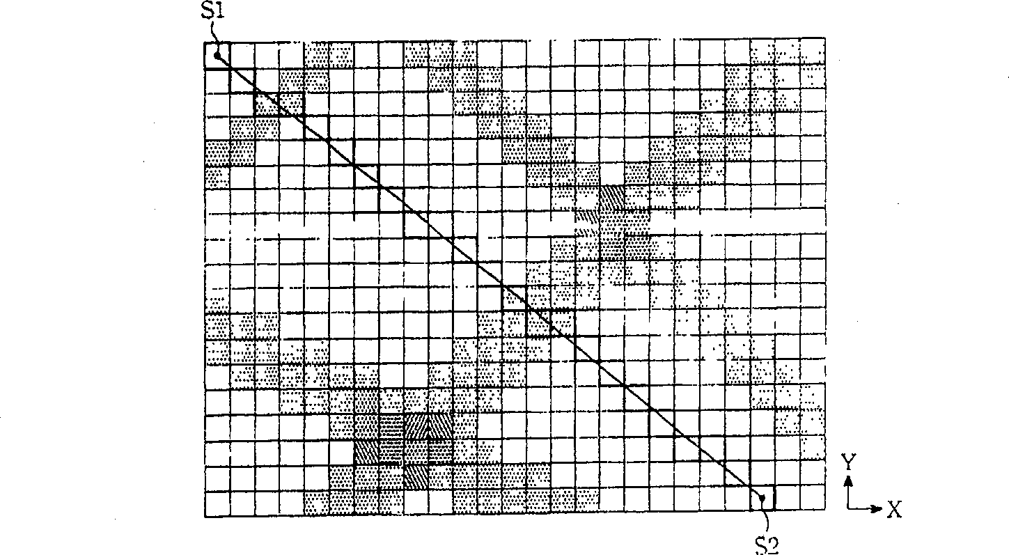
The number of data points cannot match the length of the section line S1-S2, and it is difficult to express the true cross-sectional profile
[0011] Therefore, in the existing orthogonal surface topography data map, how to quickly and accurately obtain the cross-section profile in any direction will have a significant impact on the application of non-contact topography measurement devices

Method used


Image

  • Method for forming section outline from any section lines in orthogonal surface topography map
  • Method for forming section outline from any section lines in orthogonal surface topography map
  • Method for forming section outline from any section lines in orthogonal surface topography map

Examples


Embodiment Construction

[0033] Below in conjunction with accompanying drawing, illustrate implementation process of the present invention by preferred embodiment:

[0034] Please refer to Figure 4A to Figure 4D Shown is a schematic diagram of a preferred embodiment of the method for forming a cross-sectional profile of the present invention. Figure 4Ais a known surface topography, and the a-a line segment is the section line to form a line profile. The surface topography map is divided into a plurality of orthogonally distributed pixel grids. Each pixel square has its corresponding numerical value to represent the height value.

[0035] First, if Figure 4B As shown, along the direction of the a-a section line, a column of grids to be tested (that is, the grid indicated by the dotted line in the figure) is established, and the a-a section line runs through the central position of the column of grids to be tested. The side length L of the grid to be tested is equal to the side length S of the af...


PUM


Abstract

A method for forming cross-section outline at any serif direction in orthogonal surface morphologic drawing includes dividing out multiple points to be measured by utilizing side length of check as unit on serif, forming virtual line parallel at two sides of serif, dividing out multiple virtual sections on said virtual lines and corresponding these virtual section to points to be measured, estimating out height of points to be measured based on calculating relevant value and after distance between said virtual sections and serif is weighted.

Description

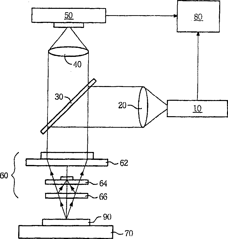
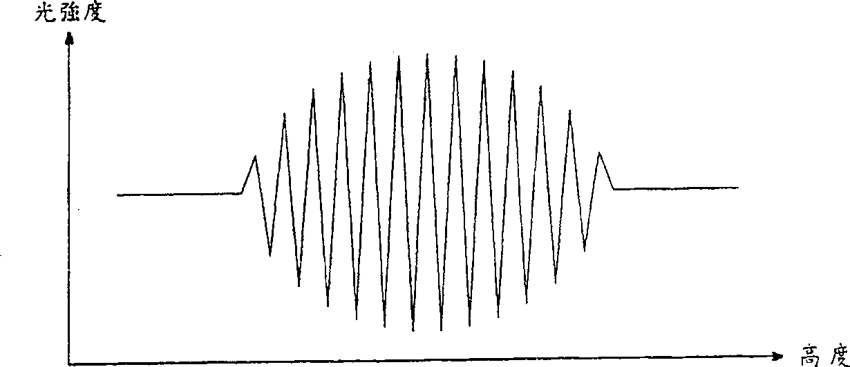
technical field [0001] The invention relates to a method for forming a line profile along a section line on a surface topography map, especially a method for forming a line profile along a section line on an orthogonal surface topography map. Background technique [0002] The shape measurement device that uses the characteristics of white light interferometry to measure the surface of the object in a non-contact manner is widely used in products that require high precision, such as: semiconductor wafers, glass panels of liquid crystal displays, etc. [0003] Please refer to figure 1 , a schematic diagram of a typical non-contact shape measurement device. Such as figure 1 As shown in , the profile measurement device has a broadband light source 10, a collimation lens (collimation lens) 20, a -45 degree beam splitter (Splitter) 30, an imaging eyepiece 40, an image sensing device 50, an interference display Micro objective lens group 60 , a scanning platform 70 and a compute...

Claims


Application Information

Patent Timeline
Patent Type & Authority Patents(China)
IPC IPC(8): G01B9/02G01B9/023
Inventor 林耀明廖界程
Owner CHROMA ATE
Learn More