Luminaire and lamellae grid for this

A technology of illuminators and thin plates, which is applied in the field of illuminators, can solve problems such as shape restrictions, and achieve the effects of small material thickness, material saving, and offsetting light loss

Inactive Publication Date: 2009-04-01
SIGNIFY HLDG BV
View PDF4 Cites 2 Cited by
  • Summary
  • Abstract
  • Description
  • Claims
  • Application Information

AI Technical Summary

Problems solved by technology

[0017] A disadvantage of the known illuminators is that, due to their shape, the sheet is larger than necessary to spread the light and cut off the light
However, this resulted in an unacceptable loss of light.
[0018] In addition to the disadvantage that the known luminaire requires a lot of rather expensive sheet metal material for the sheet, the known luminaire has the disadvantage that the galvanized sheet metal imposes restrictions on the shape of the sheet, especially the shape of the reflective surface

Method used


Image

  • Luminaire and lamellae grid for this
  • Luminaire and lamellae grid for this
  • Luminaire and lamellae grid for this

Examples


Embodiment Construction

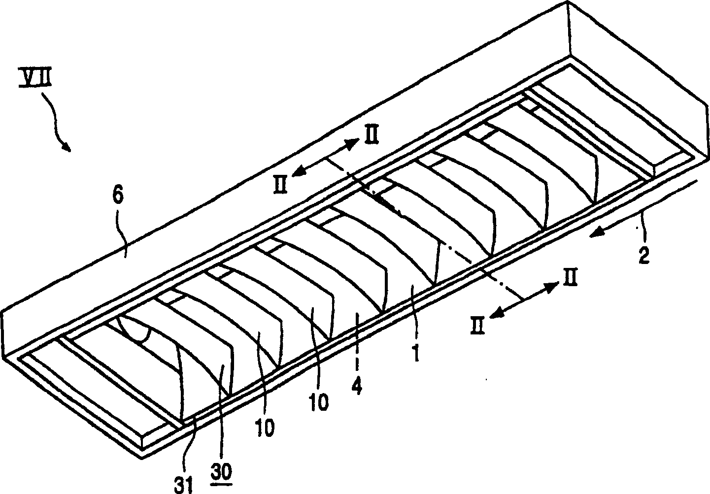
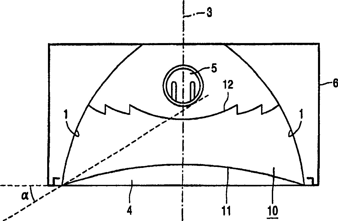
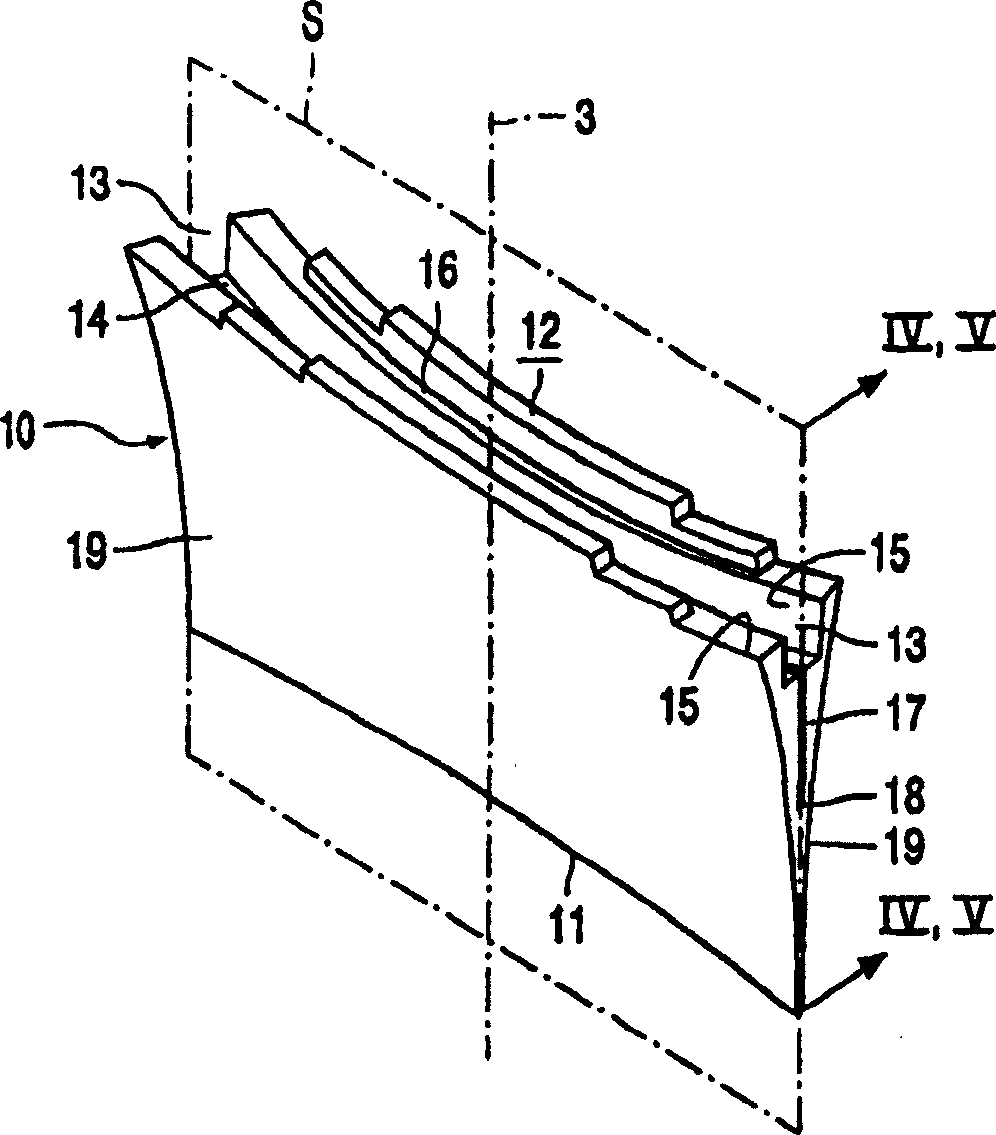
[0044] exist figure 1 and 2 , the luminaire is provided with side reflectors 1 having a longitudinal direction 2 and being mirror-symmetrical on both sides of a central plane 3 . A light emission window 4 is bounded by the side reflectors 1 and is oriented transversely to the central plane 3 . The device 5 is intended to accommodate an elongated electric lamp in the central plane 3 , in the longitudinal direction 2 of the side reflector 1 and away from the luminous emission window 4 . The device 5 is adapted to accommodate a straight tubular low pressure mercury vapor discharge vessel provided with a phosphor. like figure 2 The two identical cross-sections shown show the figure 1 Section II-II in . The device 5 is shown in this embodiment accordingly in two parts. A plurality of three-dimensional reflective sheets 10 extend transversely to the center plane between the side reflectors 1 , distributed uniformly in the longitudinal direction 2 of the side reflectors. A cu...


PUM


Abstract

The luminaire has a plurality of reflecting lamellae (10) between side reflectors (1). The lamellae (10) each have an outer edge (11), an inner surface (12) facing away from said edge (11), and a plane of symmetry (S) through the outer edge (11) and the inner surface (12). The lamellae (10) have a resin body and a recess (13) in the inner surface (12), in the plane of symmetry (S). The recess (13) has a bottom surface (14) transverse to the plane of symmetry (S) and substantially parallel walls (15) along said plane. The recess (13) may widen stepwise from the bottom plane (14) towards the inner surface (12). The lamellae (10), as compared with metal lamellae, provide a greater freedom to choose their shape and are less expensive. They nevertheless avoid the occurrence of reflections on the side reflectors, which cause unpleasant bright spots within the cut-off angle of the luminaire. The lamellae grid (30) has strips (31) interconnecting, and integral with, the lamellae (10) and is suitable for use in the luminaire.

Description

technical field [0001] The invention relates to a luminaire, which is provided with: [0002] side reflectors with a longitudinal and mirror-symmetrical position on either side of a central plane; [0003] a light emission window transverse to the central plane defined by side reflectors; [0004] means for accommodating an elongated electric lamp in the longitudinal direction of the side reflector in the central plane, away from the light emission window; [0005] A plurality of three-dimensional reflective sheets extending transversely to the central plane between the side reflectors and uniformly distributed in the longitudinal direction of the side reflectors, each of which has an outer edge adjacent to the light emission window and an inner surface facing away from the outer edge , and a plane of symmetry running through the outer edge and inner surface and transverse to the longitudinal direction of the side reflectors, such that the inner surface and the central plane...

Claims


Application Information

Patent Timeline
Patent Type & Authority Patents(China)
IPC IPC(8): F21V11/02F21V11/06F21S4/00F21S8/04F21V7/00F21V13/10F21Y103/00
CPCF21Y2103/00F21V11/02F21V11/06
Inventor P·A·J·霍坦
Owner SIGNIFY HLDG BV
Why Eureka
Try Eureka