
Method for determining envelope lines of modulation signals

An envelope and input signal technology, applied in the direction of using signal quality detectors for error detection/prevention, image communication, color TV components, etc., can solve problems such as inaccurate CCDF measurement

Inactive Publication Date: 2009-03-25
ROHDE & SCHWARZ GMBH & CO KG
View PDF7 Cites 0 Cited by
  • Summary
  • Abstract
  • Description
  • Claims
  • Application Information

AI Technical Summary

Problems solved by technology

However, this mode of operation suffers from the following disadvantages: the necessary squaring of the sampled digital values ​​results in higher-frequency spectral components
Subsequent non-ideal low-pass filtering leads to inaccurate CCDF measurements

Method used


Image

  • Method for determining envelope lines of modulation signals
  • Method for determining envelope lines of modulation signals
  • Method for determining envelope lines of modulation signals

Examples


Embodiment Construction

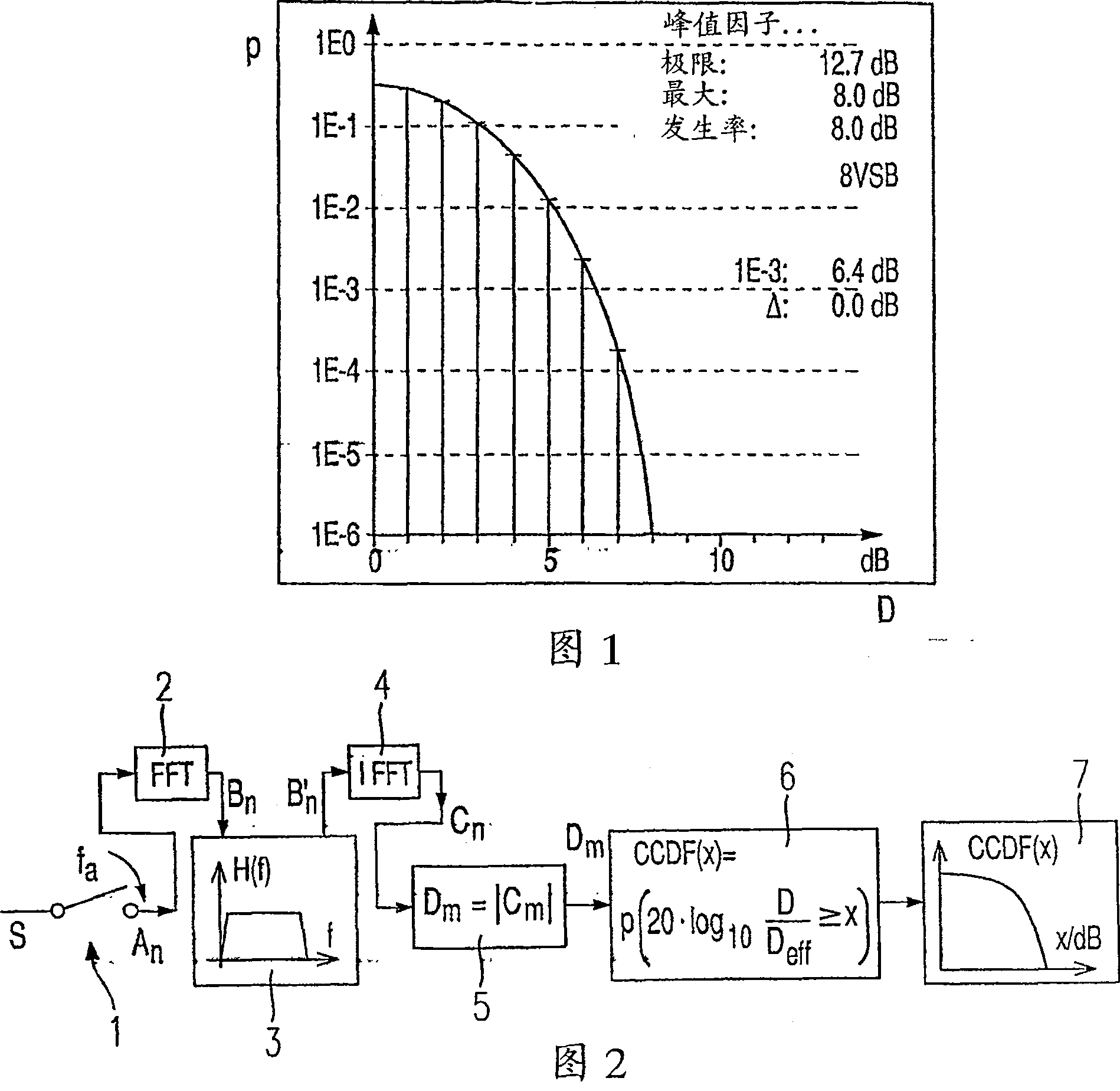
[0018] The method according to the invention is explained below by means of an application example for determining the instantaneous power of the envelope for a CCDF curve. However, as already described, the method according to the invention is not limited to this application, but is suitable for all applications requiring the instantaneous level of the envelope or a signal value such as power (ie the square of the level).

[0019] Figure 2 illustrates the method according to the invention by way of a block diagram. Wherein, the high-frequency input signal S modulated by the modulating signal is first digitally sampled by the sample and hold circuit 1 . This produces a digital sample A of the input signal S n . Then, sample A n Perform Fourier transform, for example, the fast Fourier transform (FFT) algorithm can be used to perform Fourier transform on sample An, thus producing Fourier-transformed samples (Fourier-transformed samples) B n . The Fourier transform is shown ...


PUM


Abstract

The invention relates to a method for determining the envelope of a modulated input signal (S), said method comprising the following steps: digital scan results (An) are produced by digitally scanning the input signal (S); Fourier-transformed scan results (Bn) are produced by means of the Fourier transformation (2) of the digital scan results (An); sideband-adjusted, Fourier-transformed scan results (Bn) are produced by removing the region with negative frequencies or the region with positive frequencies from the Fourier-transformed scan results (Bn); inverse-transformed scan results (Cn) are produced by means of the inverse Fourier transformation of the sideband-adjusted, Fourier-transformed scan results (B' 2); and the absolute value (Dm) of the inverse-transformed scan results (Cn) is formed.

Description

technical field [0001] The invention relates to a method for determining the envelope curve of a modulated signal, eg for determining the value of a CCDF curve. Background technique [0002] It is not only necessary to determine the envelope of the modulated signal not only in determining the Complementary Cumulative Distribution Function (CCDF), but also in other applications. The CCDF graph represents the probability that the signal level of the envelope of the analyzed signal exceeds a certain level value. According to the trajectory of the CCDF curve, parameters such as the crest factor can be determined, and the crest factor represents the ratio of the power at the peak of the signal to the average power. The crest factor is used to help the operator of a modulated high frequency transmitter determine the optimum modulation for the transmitter amplifier. On the one hand, it is desirable to transmit power as high as possible so that the signal-to-noise ratio at the rec...

Claims


Application Information

Patent Timeline
Patent Type & Authority Patents(China)
IPC IPC(8): H04N17/00H04N5/455H04B17/00H04L1/20H04N5/38
CPCH04N5/455H04N17/00H04N5/38H04L1/206H04B17/0002H04B17/10
Inventor 马丁·霍夫梅斯特
Owner ROHDE & SCHWARZ GMBH & CO KG
Learn More