
High speed transfer system

A technology for high-speed transmission and control of equipment, applied in parts, electrical components, emergency protection circuit devices, etc. of emergency protection devices, which can solve problems such as increased cost and increased hardware complexity

Inactive Publication Date: 2009-03-11
ABB (SCHWEIZ) AG
View PDF3 Cites 0 Cited by
  • Summary
  • Abstract
  • Description
  • Claims
  • Application Information

AI Technical Summary

Problems solved by technology

Therefore, the complexity of the hardware needs to be increased, and the cost increases accordingly

Method used


Image

  • High speed transfer system
  • High speed transfer system
  • High speed transfer system

Examples


Embodiment Construction

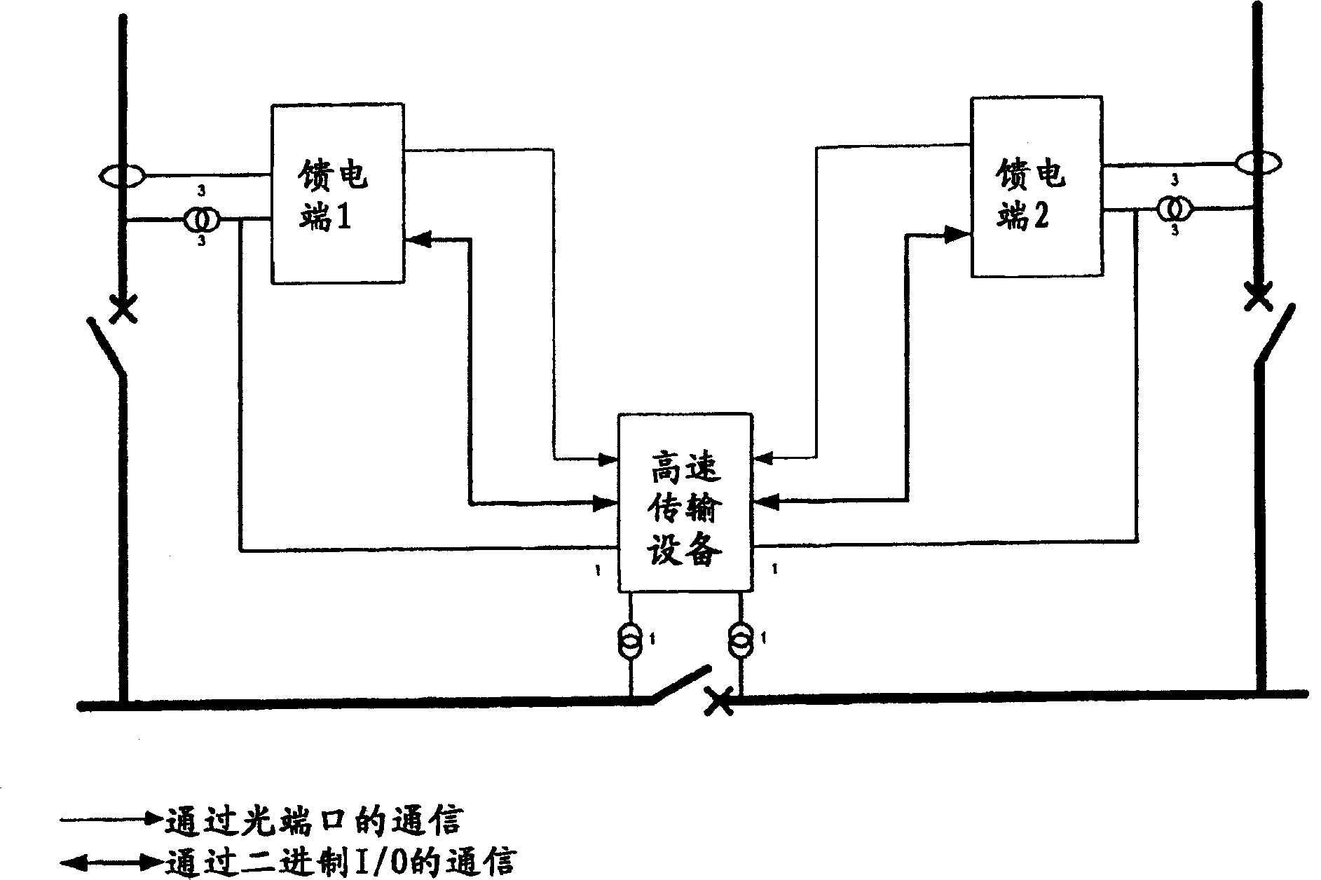
[0030] figure 1 with figure 2 A detailed description of the functionality is given. Each feeder protection and control device takes current and voltage measurements from the feeder buses to detect any possible faults on those buses. Such faults are detected by implementing specific protection functions capable of distinguishing the direction of the fault. In fact, high-speed transmission systems do not necessarily intervene in the failure of electrical loads. The same voltage measurements are also obtained from a third protection and control device, which enables high-speed transmission system coordination. Such measurements are necessary in order to identify the correct moment at which switchgear operation must be performed. This is done to minimize any current and voltage overshoots.

[0031] High-speed transmission system logic circuit is different from figure 1 with figure 2 The two situations indicated.

[0032] figure 1 In the shown case, since the fault oc...


PUM


Abstract

A High Speed Transfer System which comprises three Protection and Control devices. A first and a second of said Protection and Control devices are used for failure detection on the feeder bus-bar; the third of said Protection and Control devices is used for the High Speed Transfer System co-ordination functionalities.

Description

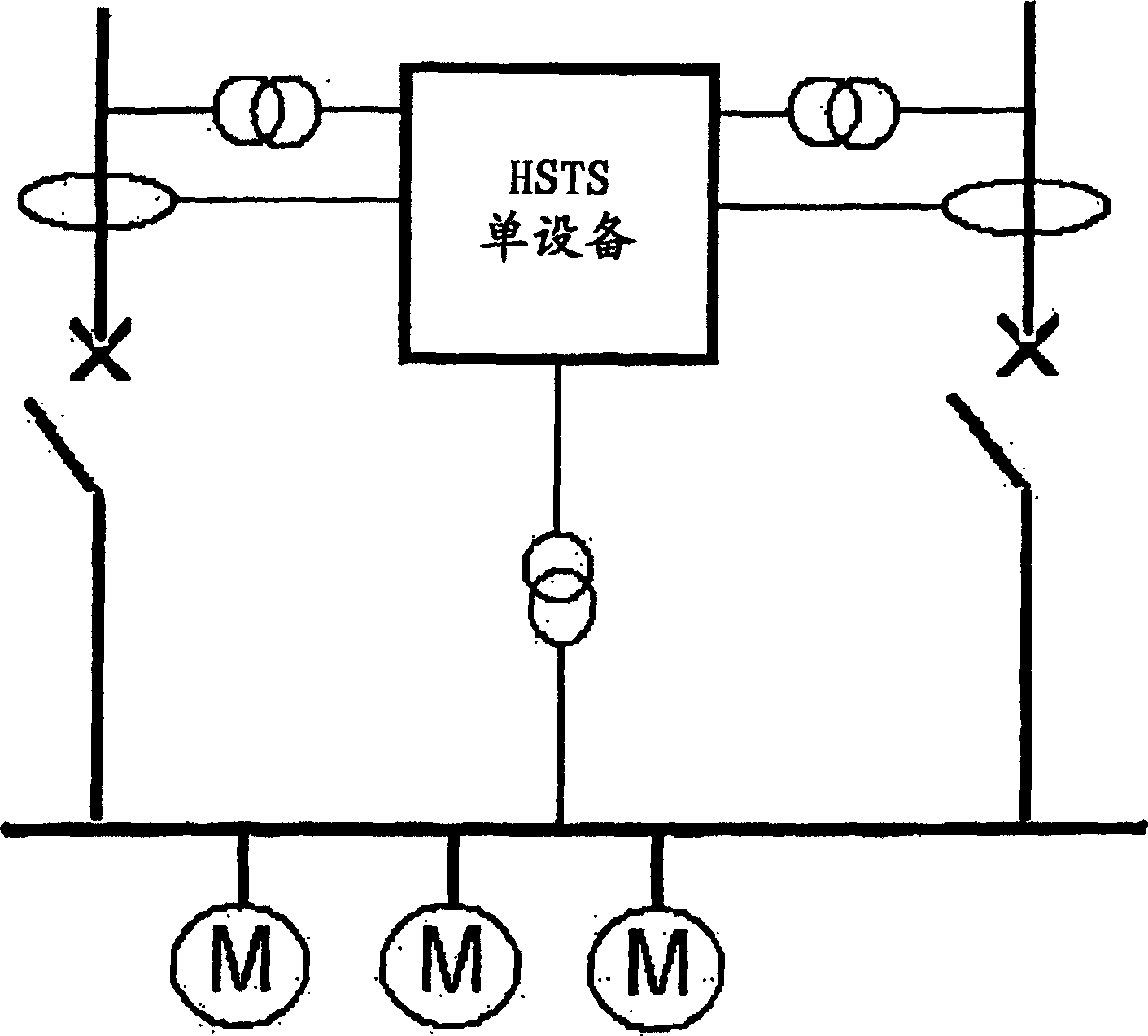
technical field [0001] The present invention relates to a high-speed transmission system for power distribution and, in particular, to a high-speed transmission system for protection and control of power distribution networks. Background technique [0002] The typical structure of high-speed transmission system is as follows: image 3 As shown, a single device performs the function of the high-speed transmission system. In particular, specific devices protect the two feeder buses by performing specific protection functions. [0003] In the event of a failure of one feeder bus, such equipment sends a trigger signal through a conventional input channel to the high speed transmission system equipment, which processes this information along with other information about the bus voltage. As the voltage is applied to the switching device then the high speed transmission system device is activated. [0004] The device is able to obtain digital and analog input signals by means of ...

Claims


Application Information

Patent Timeline
Patent Type & Authority Patents(China)
IPC IPC(8): H02H7/26H02H1/00H02H7/30
CPCH02H1/0069H02H7/266H02H7/30
Inventor 卢西亚诺·迪马约拉尔夫·克鲁姆安德烈·安登纳费比欧·加特利安迪亚·克雷斯皮
Owner ABB (SCHWEIZ) AG
Learn More