
Mixed dust separating device

A kind of dust removal device and hybrid technology, applied in the direction of combination device, steam flow control, electrode structure, etc., can solve the problems of dust removal filter damage, increase of filter pressure loss, failure to work normally, etc.

Inactive Publication Date: 2008-12-24
KOREA INST OF ENERGY RES
View PDF3 Cites 0 Cited by
  • Summary
  • Abstract
  • Description
  • Claims
  • Application Information

AI Technical Summary

Problems solved by technology

However, there is also a problem with the filter-type dust collector: as the dust filtering work progresses, the dust layer trapped on the filter will become thicker and thicker, so the pressure loss of the filter will increase, thus cause the filter not to work properly
However, since the discharge electrode of the electrostatic precipitator generates electric sparks, the dust filter is easily damaged and cannot work normally, so there are also problems.

Method used


Image

  • Mixed dust separating device
  • Mixed dust separating device
  • Mixed dust separating device

Examples


Embodiment Construction

[0032] A hybrid dust removal device according to a preferred embodiment of the present invention will be described below.

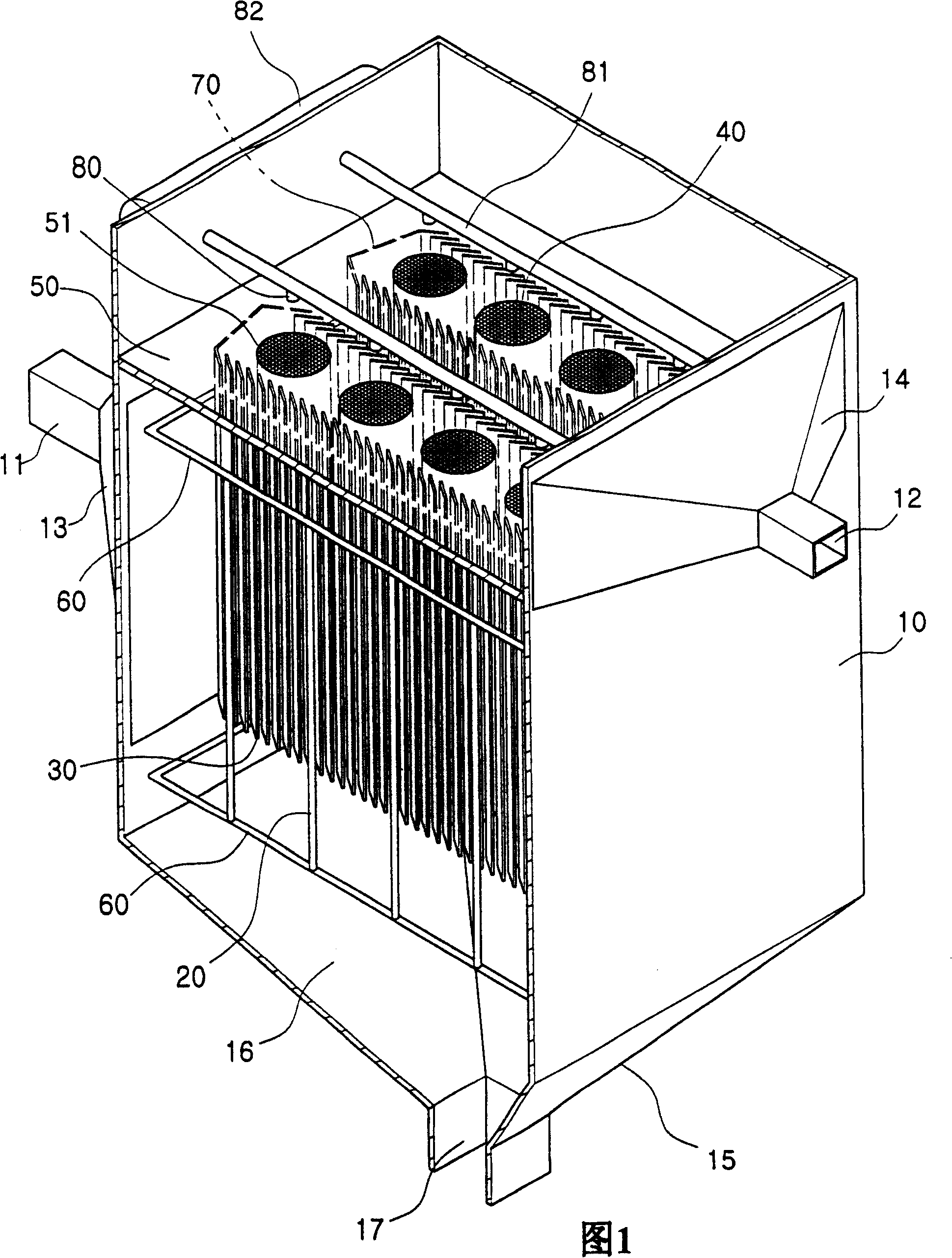
[0033] Fig. 1 is an open perspective view showing the hybrid dust removal device of the preferred embodiment.

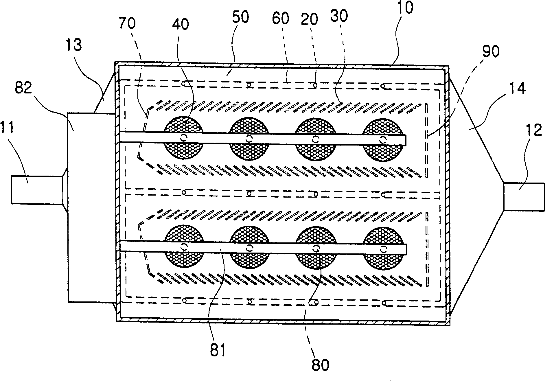
[0034] As shown in FIG. 1 , the hybrid dust removal device includes a rectangular housing 10 . The rectangular housing 10 has an inflow channel 11, which is connected with a section of inflow expander pipe 13, which is arranged at the lower part 10 of one side of the housing 10; and has an outflow channel 12, which is connected with a section of outflow expander pipe The flow reducer 12 is connected, and the reducer is arranged on the upper part of the other side of the casing 10 .

[0035] Inside the housing 10, a horizontal partition 50 is provided with a plurality of filter mounting holes 51 on the partition. A plurality of dust removal filters 40 are respectively inserted into these mounting holes 51 , and the filters 40 extend downward fr...


PUM


Abstract

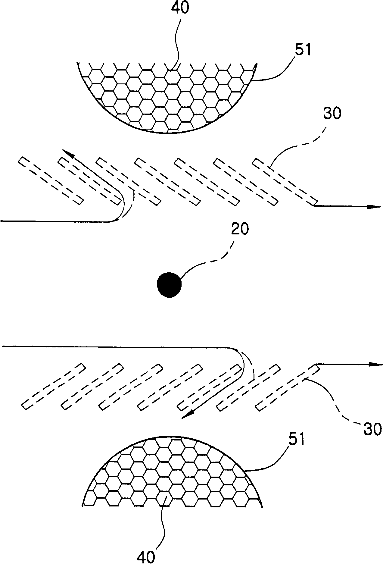
PURPOSE: A combination type dust collecting apparatus is provided which maintains high dust collecting performance of the dust collecting apparatus and substantially extends performance and life time of dust collecting filter at the same time. CONSTITUTION: In a combination type dust collecting apparatus in which discharge electrodes(20), collecting electrodes(30) and dust collecting filters(40) are installed inside a main body(10) having inlet(11) and outlet(12), the combination type dust collecting apparatus comprises a splitting plate(50) installed inside the main body between the inlet and outlet; a plurality of mounting holes(51) formed on the splitting plate with being spaced apart from each other in a certain distance; cylindrical dust collecting filters one end of which is insertingly adhered to the mounting holes in a lower part of the splitting plate, and which are horizontally installed in a plurality of rows; a plurality of collecting electrodes which are adhered to the lower surface of the splitting plate at both sides of the dust collecting filters with being spaced apart from each other, and which are arranged slantly and horizontally in a row; a plurality of discharge electrodes which are spaced apart from each other at an outer side of the collecting electrodes and adhered to a mounting ring(60) vertically installed inside the main body in a plurality of rows; guiding portions(70) installed at the lower surface of the splitting plate in front of the collecting electrodes and dust collecting filters corresponding to the inlet; and an outlet installed at one side of the main body in an upper part of the splitting plate.

Description

technical field [0001] The invention relates to a hybrid dust removal device, which includes a dust removal filter, a dust removal electrode and a discharge electrode, and the device can not only function as a filter type dust remover, but also as an electrostatic dust remover, more specifically In other words, the present invention relates to a hybrid type dedusting device which has greatly improved dedusting performance and provides a dedusting filter with much longer operating life and improved performance. Background technique [0002] Generally, places that consume a large amount of combustion gas, such as pulverized coal-fired power plants, use electrostatic precipitators. On the other hand, those places that deal with small or medium quantities of combustion gases or dusty gases use filter-type dust collectors. . [0003] However, as more and more low-sulfur coal is used as fuel, the resistivity of the smoke exhausted by combustion increases gradually. This not only...

Claims


Application Information

Patent Timeline
Patent Type & Authority Patents(China)
IPC IPC(8): B01D50/00B03C3/36B03C3/155B03C3/40B03C3/41B03C3/47B03C3/80B03C3/82
CPCB01D46/0032B01D46/023B01D46/04B01D50/00B03C3/017B03C3/41B03C3/47B03C3/80B03C3/82
Inventor 孙宰翼朴永玉朴石周林正焕金相道催浩竞朴贤设
Owner KOREA INST OF ENERGY RES
Learn More