Electromagnetic oven

A technology of induction cooker and furnace cavity, which is used in household stoves/stoves, electric heating fuel, household heating, etc. It can solve the problems of poor cooling effect, shorten the service life of circuit boards, affect the appearance and other problems, achieve reasonable and meticulous organization, and improve heat dissipation. The effect, the effect of less wind waste

Inactive Publication Date: 2008-12-03
汕头市夏野电器有限公司
View PDF8 Cites 0 Cited by
  • Summary
  • Abstract
  • Description
  • Claims
  • Application Information

AI Technical Summary

Problems solved by technology

[0002] During the working process of the induction cooker, the fan needs to continuously blow and dissipate the heat from the circuit board and the wire reel. The circuit board is arranged at the lower part of the furnace cavity, and the wire reel is arranged at the upper part of the furnace chamber. The traditional induction cooker generally sets the air inlet of the furnace chamber at Correspondingly, the installation direction of the fan is facing upwards on the bottom of the furnace cavity. This traditional structure of the induction cooker has several disadvantages: 1. The fan faces upwards, and the air inlet is set at the lower part of the furnace body or even the bottom shell, so it is easy to Inhale the dust on the desktop or other sundries such as cigarette packaging tinfoil into the oven cavity, which may easily damage or short-circuit the circuit components in the oven cavity, causing safety hazards; in addition, it is easy to suck up the disposable plastic film on the dining table, Block the air inlet; 2. Due to the fact that the fan is facing upwards and lacks structural measures to guide the wind force to the lower part of the furnace cavity, the wind force in the lower part of the furnace cavity is small, and the proportion of air flow between the upper part and the lower part of the furnace cavity is unreasonably distributed, that is, the cooling of the circuit board. The ratio of the airflow and the airflow cooling the reel cannot be reasonably distributed, and the heat dissipation effect has the problem of "strong at the top and weak at the bottom"; and the circuit board located in the lower part of the furnace cavity is a heat-resistant element, and its insufficient heat dissipation effect will shorten the service life of the circuit board 3. The organization of the air flow route is unreasonable and not meticulous, the wind power is wasted, and the overall cooling effect is poor: 1. Because the horizontal positions of the wire reel and the circuit board do not completely overlap or even do not overlap at all, and the wire reel is close to the furnace cavity Therefore, in the air flowing through the position of the coil, the flow near the lower part of the furnace cavity has no heat dissipation effect; similarly, since the circuit board is arranged at the lower part of the furnace cavity, in the air flowing from the position of the circuit board, the flow close to the furnace The flow in the upper part of the chamber also does not play a role in heat dissipation; 2. The coil mainly dissipates heat through its upper surface, but the coil area is relatively large, forming a long and narrow gap between the upper surface of the coil and the panel of the induction cooker, and The spatial location is much wider than the gap, so the wind is not easy to enter the gap, and most of the wind will tend to bypass the wider peripheral position outside the coil, resulting in waste of wind power
[0003] In order to overcome the above-mentioned shortcoming, people try to propose improvement scheme, for example Chinese patent CN200420064667. There are two problems in the above-mentioned structure. First, the raised part not only affects the appearance, but also affects the convenience of use; second, the air flows through the wire reel first, and then flows through the circuit board, so that the air flow passing through the circuit board has been heated by the wire reel. Therefore, the heat dissipation effect on the circuit board is still poor

Method used


Image

  • Electromagnetic oven
  • Electromagnetic oven
  • Electromagnetic oven

Examples


Embodiment Construction

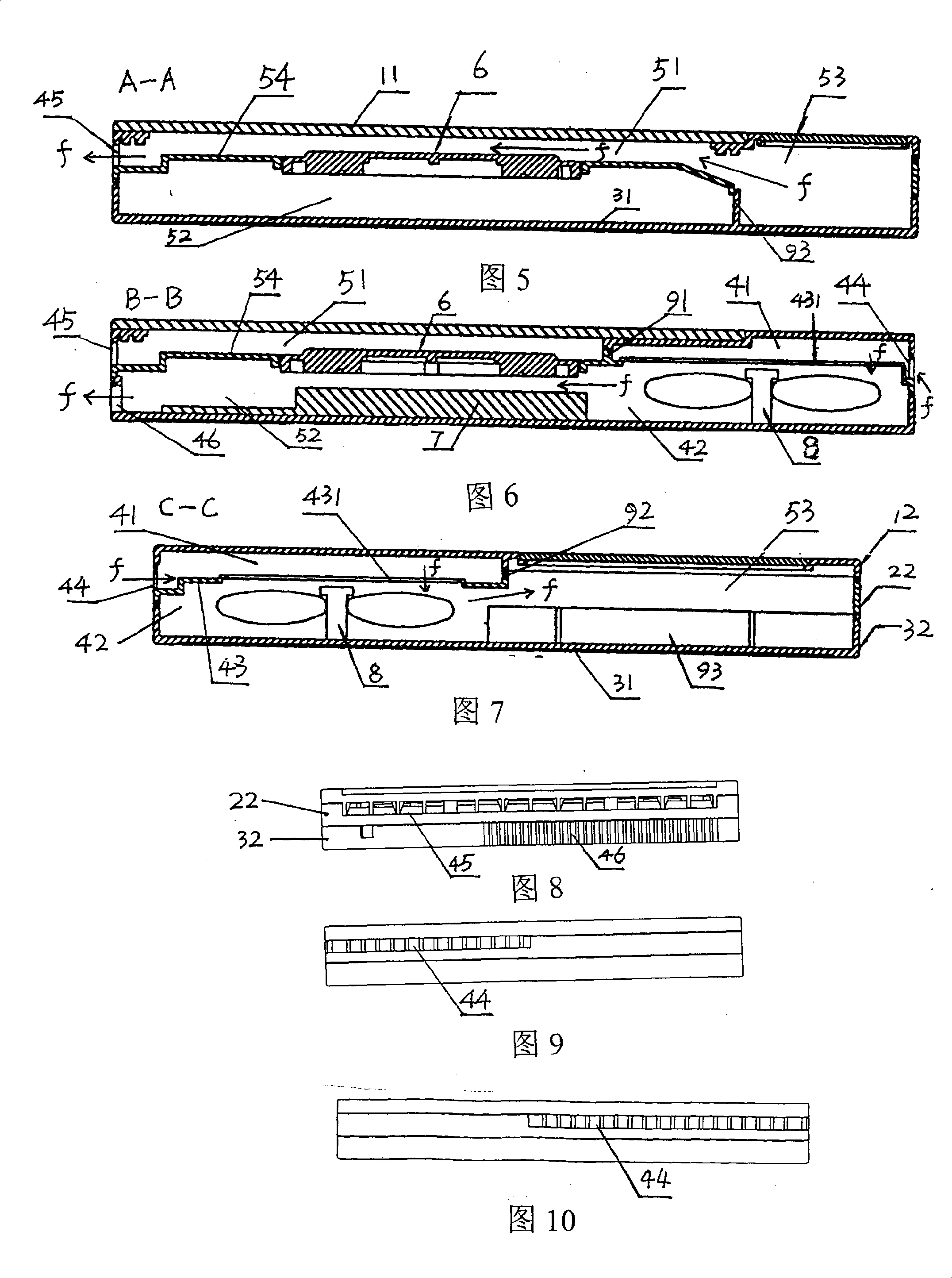
[0033] figure 1 , Fig. 2, Fig. 3, the shell of the induction cooker shown in Fig. 4 is formed by combination of upper shell, middle shell and lower shell, wherein the upper shell is assembled by microcrystalline plate 11, upper side plate 12, glass plate 13, and lower shell The bottom plate 31 and the lower side plate 32 are integrally formed, the middle shell is also provided with the middle side plate 22, the upper side plate 12, the middle side plate 22, and the lower side plate 32 are assembled to form the side wall of the whole induction cooker, the upper shell, The middle shell and the lower shell are enclosed to form a furnace cavity.

[0034] Figure 4, Figure 5, Figure 6, Figure 13 As shown, the furnace chamber is divided into a fan chamber and a main chamber, and the main chamber is further divided into an upper main chamber 51, a lower main chamber 52, and an air guide chamber 53, the upper main chamber 51 is located above the lower main chamber 52, and the glass p...


PUM


Abstract

The invention relates to an electromagnetic furnace, which comprises: furnace chamber with coil disc, circuit board with hear radiator, and fan, wherein said furnace chamber has wind outlet; and the invention is characterized in that: the furnace chamber is divided into main furnace chamber and fan room; the fan room is divided into upper and lower small rooms, with horizontal baffle plate between them; the horizontal baffle plate has round hole at the middle, whose center is on the central axle of blade of fan; the size of round hole is matched with fan; the fan is downwards mounted; there is a separate baffle plate between the upper small room and the main furnace chamber; the lower small room is through to the main furnace chamber; the upper small room has the wind inlet through to the outer space of furnace. The wind inlet will not absorb dust or metal chip, to blow the airflow to the surface of coil disc, with better heat radiation.

Description

technical field [0001] The invention belongs to an electromagnetic cooker. Background technique [0002] During the working process of the induction cooker, the fan needs to continuously blow and dissipate the heat from the circuit board and the wire reel. The circuit board is arranged at the lower part of the furnace cavity, and the wire reel is arranged at the upper part of the furnace chamber. The traditional induction cooker generally sets the air inlet of the furnace chamber at Correspondingly, the installation direction of the fan is facing upwards on the bottom of the furnace cavity. This traditional structure of the induction cooker has several disadvantages: 1. The fan faces upwards, and the air inlet is set at the lower part of the furnace body or even the bottom shell, so it is easy to Inhale the dust on the desktop or other sundries such as cigarette packaging tinfoil into the oven cavity, which may easily damage or short-circuit the circuit components in the ove...

Claims


Application Information

Patent Timeline
Patent Type & Authority Patents(China)
IPC IPC(8): F24C7/00H05B6/12
Inventor 陈梓平
Owner 汕头市夏野电器有限公司
Why Eureka
Try Eureka