
Disinfection cabinet with rotatable ultraviolet disinfecting tube

A technology for ultraviolet disinfection and disinfection cabinets, which is applied in the field of disinfection cabinets. It can solve the problems of unreasonable placement of ultraviolet lamps, complicated rotating mechanisms, and inconvenient use of disinfection machines. It achieves good disinfection effects, high ray utilization, and The effect of simple structure

Active Publication Date: 2008-12-03
QINGDAO HAIER WISDOM KITCHEN APPLIANCE CO LTD +1
View PDF6 Cites 0 Cited by
  • Summary
  • Abstract
  • Description
  • Claims
  • Application Information

AI Technical Summary

Problems solved by technology

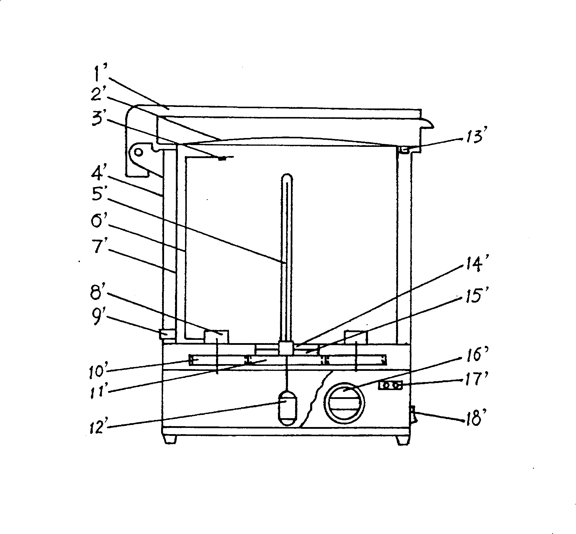
The disinfection machine in this comparison document is mainly used in the beauty and hairdressing industry. The ultraviolet lamp tube 5' installed in the disinfection machine can be rotated, and is mainly used to disinfect hairdressing and beauty products such as combs, scissors, and tweezers. Generally, they are small items. Therefore, in this comparison document, the structure that the ultraviolet lamp tube and the sterilized items are rotated at the same time is adopted. However, for some large items that cannot be hung and are not easy to rotate, the sterilizer can be used It is inconvenient and limited, and the rotating mechanism disclosed in the disinfection cabinet is relatively complicated, and the setting position of the ultraviolet lamp is not very reasonable, and further improvement is required by those skilled in the art

Method used


Image

  • Disinfection cabinet with rotatable ultraviolet disinfecting tube
  • Disinfection cabinet with rotatable ultraviolet disinfecting tube
  • Disinfection cabinet with rotatable ultraviolet disinfecting tube

Examples


Embodiment 1

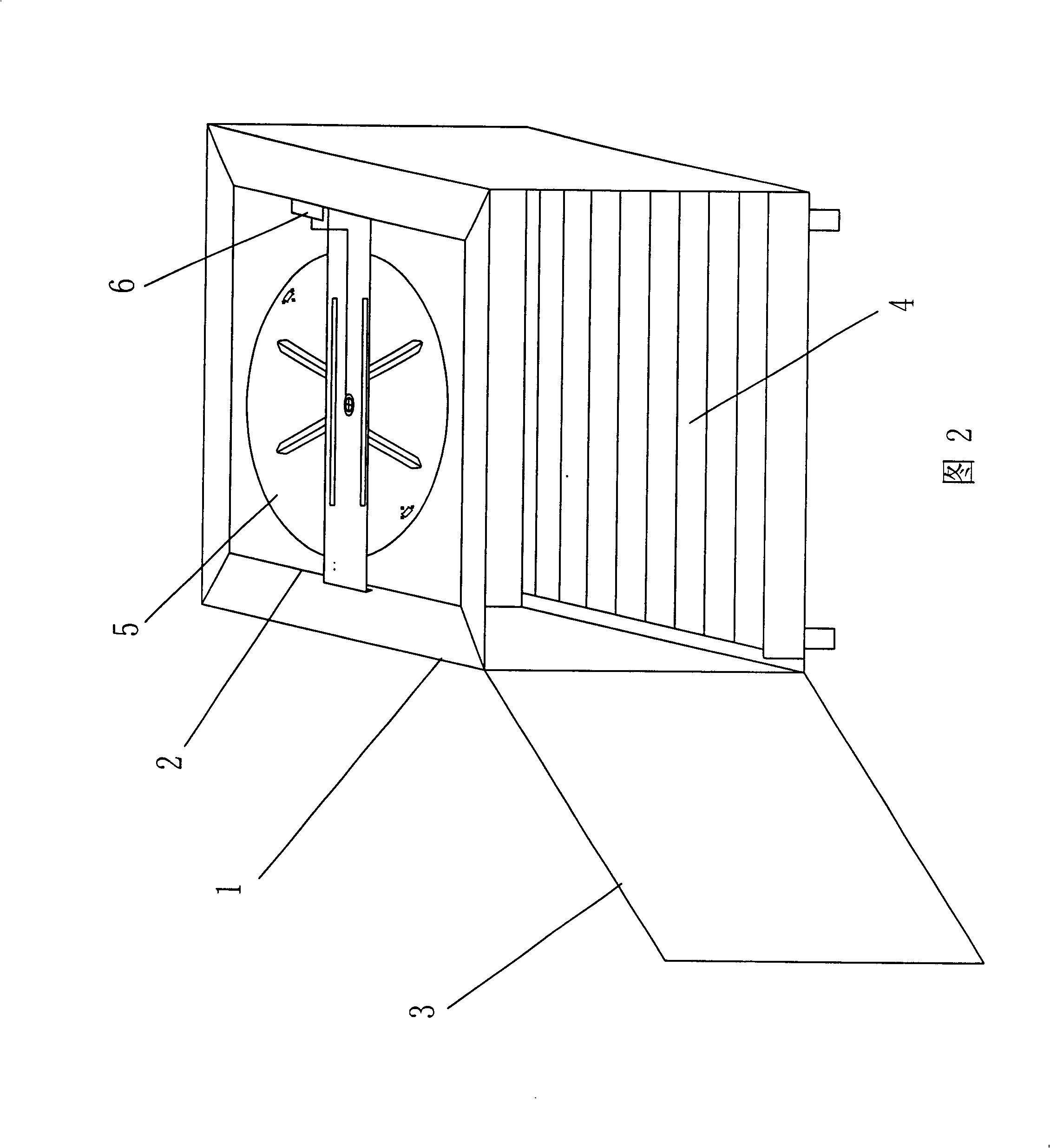
[0036] In the disinfection cabinet with a rotatable ultraviolet disinfection lamp tube, the rotating lamp holder 5 includes a circular, rotatable light-rotating reflection plate 51 for installing and arranging the ultraviolet lamp tube.

[0037] As a method, the above-mentioned optically active reflection plate 51 can be directly and rotatably installed on the top of the box body 2. Because this arrangement method is simple in structure, the structure of the drawings is omitted. Those skilled in the art can obtain the structure. Firstly, a circular slot with an area smaller than the area of ​​the optically active reflector is set on the top of the casing 2, then a chute is set on the periphery of the empty slot, a slide rail is set on the edge of the optically active reflector, and then the The slide rails fit into the chute on the top of the cabinet; Figure 4 As shown, the optically active reflector 51 includes a rotatable disk 514, and at the center of the optically active...

Embodiment 2

[0040] Most of the structures in this embodiment are the same as those in Embodiment 1, except that the structure of the rotating lamp holder 5 is slightly different from Embodiment 1.

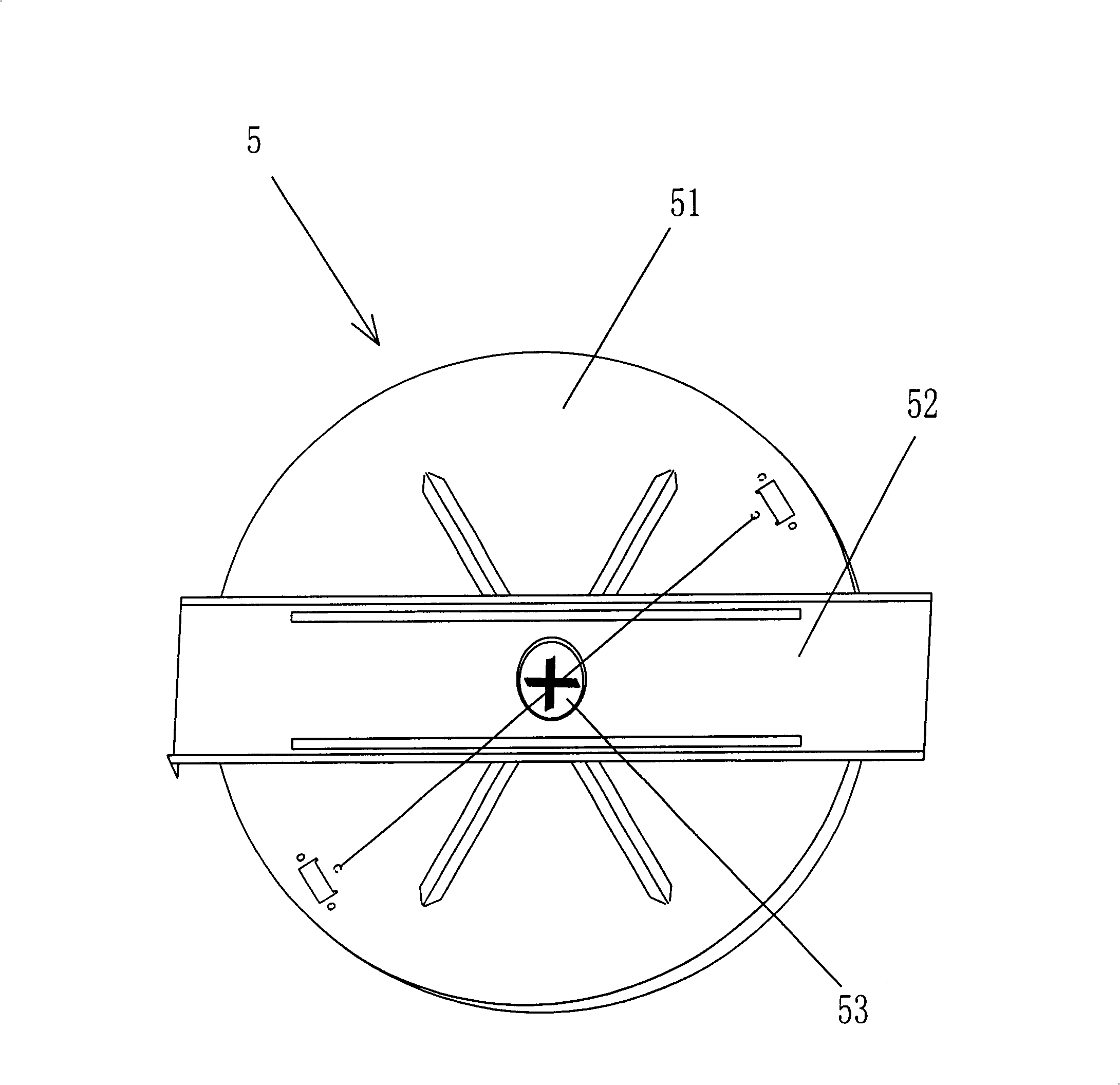
[0041] As another way, in the disinfection cabinet with the rotatable ultraviolet disinfection lamp tube, as image 3 As shown, the rotating lamp holder 5 includes an optically rotating reflection plate 51 and a rotating lamp holder base plate 52 .

[0042] Such as Figure 3-Figure 5 As shown, the rotating lamp holder 5 further includes a strip-shaped rotating lamp holder base plate 52 for fixing the optical rotation reflector 51. The rotating lamp holder base plate 52 is fixed on the top of the box body. The central axis 53 is rotatably fixed on the optical reflection plate 51 .

[0043] In the disinfection cabinet with a rotatable ultraviolet disinfection lamp, the light-rotating reflection plate 51 includes a rotatable disc 514, and at least two reinforcing ribs 511 are evenly distributed...


PUM


Abstract

The invention discloses a sterilizing cabinet with rotatable ultraviolet sterilizing tube, which comprises the following parts: case, cabinet, door, baffle shelf, control circuit in the case, rotary tube rack on the top of cabinet, power source in the case to drive rotary tube rack, wherein the output shaft of power source connects rotary tube rack, the rotary ultraviolet tube can sterilize each part of cabinet evenly.

Description

technical field [0001] The invention relates to a disinfection cabinet, in particular to a disinfection cabinet with a rotatable ultraviolet disinfection lamp tube. Background technique [0002] With the rapid development of science and technology and the improvement of people's living standards, disinfection cabinets have been widely used in people's daily lives. The disinfection cabinet is an electronic disinfection cabinet, also called an electric heating disinfection cabinet and an electronic tableware disinfection cabinet. It is a new type of kitchen appliance integrating disinfection, drying and storage. After years of development, the disinfection cabinet has been used by more and more families. accept. The disinfection cabinet has good sterilization effect, strong penetrating power, and no chemical residues, which cannot be achieved by general high-temperature disinfection. Moreover, the refrigerator-like door of the disinfection cabinet is more airtight than ordin...

Claims


Application Information

Patent Timeline
Patent Type & Authority Patents(China)
IPC IPC(8): A61L2/10
Inventor 申伟斌温学忠王成久张学策马少云
Owner QINGDAO HAIER WISDOM KITCHEN APPLIANCE CO LTD
Learn More