
High strength panel

A panel and floor technology, which is applied to local raised floors, building components, buildings, etc., can solve the problems of large vertical and horizontal arrangement interval of reinforcing ribs 206, reduced supporting force, accelerated damage and cracking, etc.

Active Publication Date: 2008-11-05
HAEKWANG
View PDF5 Cites 0 Cited by
  • Summary
  • Abstract
  • Description
  • Claims
  • Application Information

AI Technical Summary

Problems solved by technology

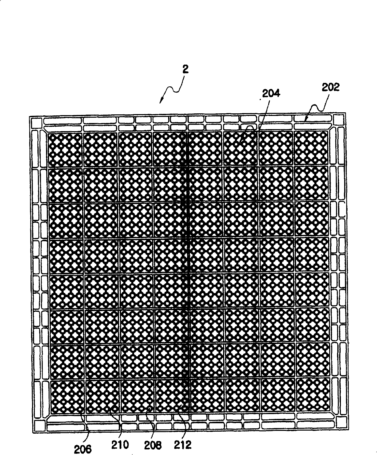
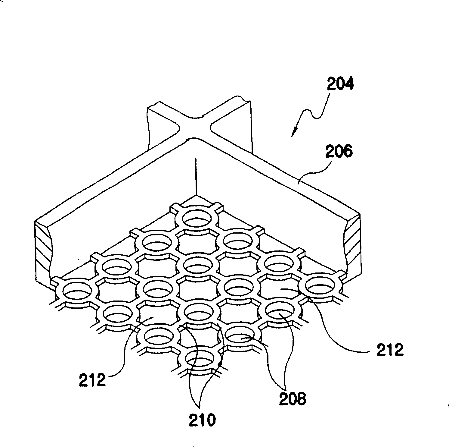
[0009] In addition, the vertical and horizontal intervals of the main reinforcing ribs 206 of the traditional floor panel are large, and the circular grooves 208 are concentrated in the spaces between them.
Therefore, when the vertical load from the top and the eccentric load from the side are transmitted to the middle part between the main ribs 206 formed in a grid shape, the circular groove 208 formed in the center and the The support force of the cross-shaped groove 212 relative to the load is reduced, and there are problems such as accelerating the damage and cracking of this part.

Method used


Image

  • High strength panel
  • High strength panel
  • High strength panel

Examples


Embodiment Construction

[0036] Next, floor panels according to preferred embodiments of the present invention will be described in detail with reference to the accompanying drawings.

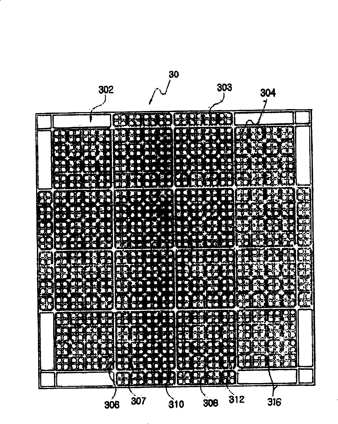
[0037] image 3 It is a plan view which shows the state which turned over the floor panel which is preferable in this invention. Figure 4 will be image 3 An enlarged perspective view of an enlarged representation of a portion of the panel, Figure 5 yes Figure 4 Top view of the panel shown. Figure 6 is a cross-sectional view of a floor panel of a preferred embodiment of the present invention, Figure 7 will be image 3 A top view of an enlarged representation of a portion of the panel, Figure 8 is along Figure 7 The line A-A is taken from the cutaway view.

[0038] As shown in these drawings, in the floor panel 30 of the preferred embodiment of the present invention, the edge rib 316 constituting the panel edge portion 302 has been reinforced in thickness compared with the existing panel, and it has a ta...


PUM


Abstract

The present invention relates to a high strength panel used in floor materials of cleaning equipment such as semiconductor dustless room etc. The high strength panel provides brim stiffener and main stiffener on the edge of the panel, wherein the centralized intensity is greatly increased with each point of the panel by forming a supporting force among the stiffeners. In addition, a circular groove and a circular stiffener surround the groove are formed on the bottom of the panel which effectively bearing the vertical load and eccentric load applied on the entire panel, and the load transported from upside is dispersed averagely on the entire panel instead of be assembled together.

Description

technical field [0001] The present invention relates to a floor panel used as a floor material for cleaning equipment such as semiconductor clean rooms. In each place of the panel, the concentrated strength is significantly increased. In addition, the circular groove formed on the bottom surface of the panel and the circular rib surrounding the circular groove can effectively support the vertical force applied to the entire panel. Load and eccentric load, and the load from above will not be concentrated in one place, but evenly distributed on the entire panel. Background technique [0002] As we all know, the floor of the clean room with various special devices for production and research in the manufacturing room of high integrated circuits such as semiconductors, the transgenic engineering research room, etc. has a double floor system. While absorbing external fine dust, dust, tiny particles, etc., the load of various special devices is evenly distributed, and the load co...

Claims


Application Information

Patent Timeline
Patent Type & Authority Patents(China)
IPC IPC(8): E04F15/024E04C2/52E04C2/38
Inventor 金在源
Owner HAEKWANG
Learn More