Revolving switch valve

A switching valve, rotary technology, applied in the direction of multi-way valves, valve devices, engine components, etc., can solve the problems that the sliding valve core cannot realize stable switching, and the intelligent electric head cannot realize intelligent switching, so as to improve the reliability of operation Performance and service life, convenient use and maintenance, and stable lubricating oil pressure

Inactive Publication Date: 2008-09-17
大连创思福液力偶合器成套设备有限公司
View PDF7 Cites 0 Cited by
  • Summary
  • Abstract
  • Description
  • Claims
  • Application Information

AI Technical Summary

Problems solved by technology

[0003] Aiming at the above problems, the present invention provides a rotary electric switching valve, which is composed of an intelligent electric head, a balanced pressure rotary valve core, a relief valve and a valve body, etc., and is mainly used for being supported by sliding bearings or for external lubrication. The speed-regulating hydraulic coupling of the oil can ensure that the main motor of the speed-regulating hydraulic coupling can start without load and switch the oil circuit system without disturbance; The problem that it cannot be combined with the intelligent electric head and cannot realize intelligent switching, and it helps to improve the reliability and service life of the coupling operation, as well as reduce the cost of equipment, operation and maintenance

Method used


Image

  • Revolving switch valve
  • Revolving switch valve
  • Revolving switch valve

Examples


Embodiment Construction

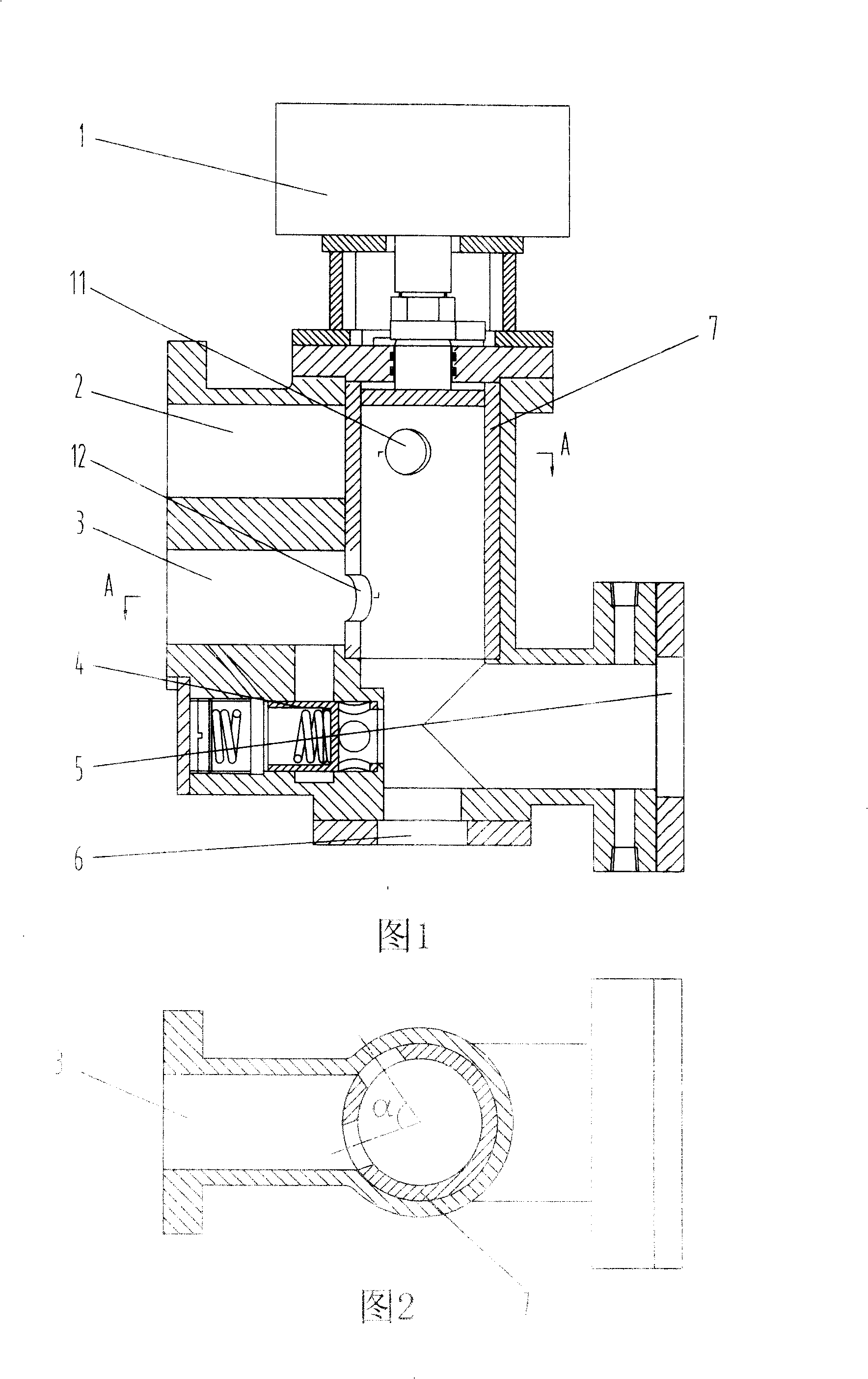
[0016] As shown in FIG. 1 , the rotary spool type intelligent electric switching valve of the present invention will be described with reference to FIG. 2 .

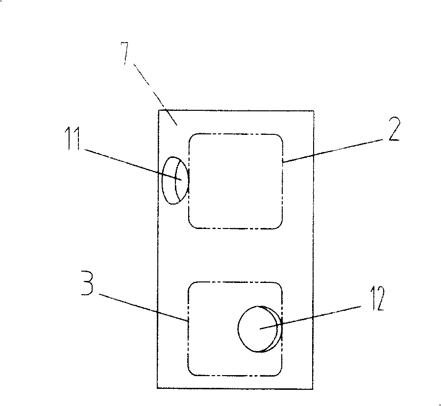
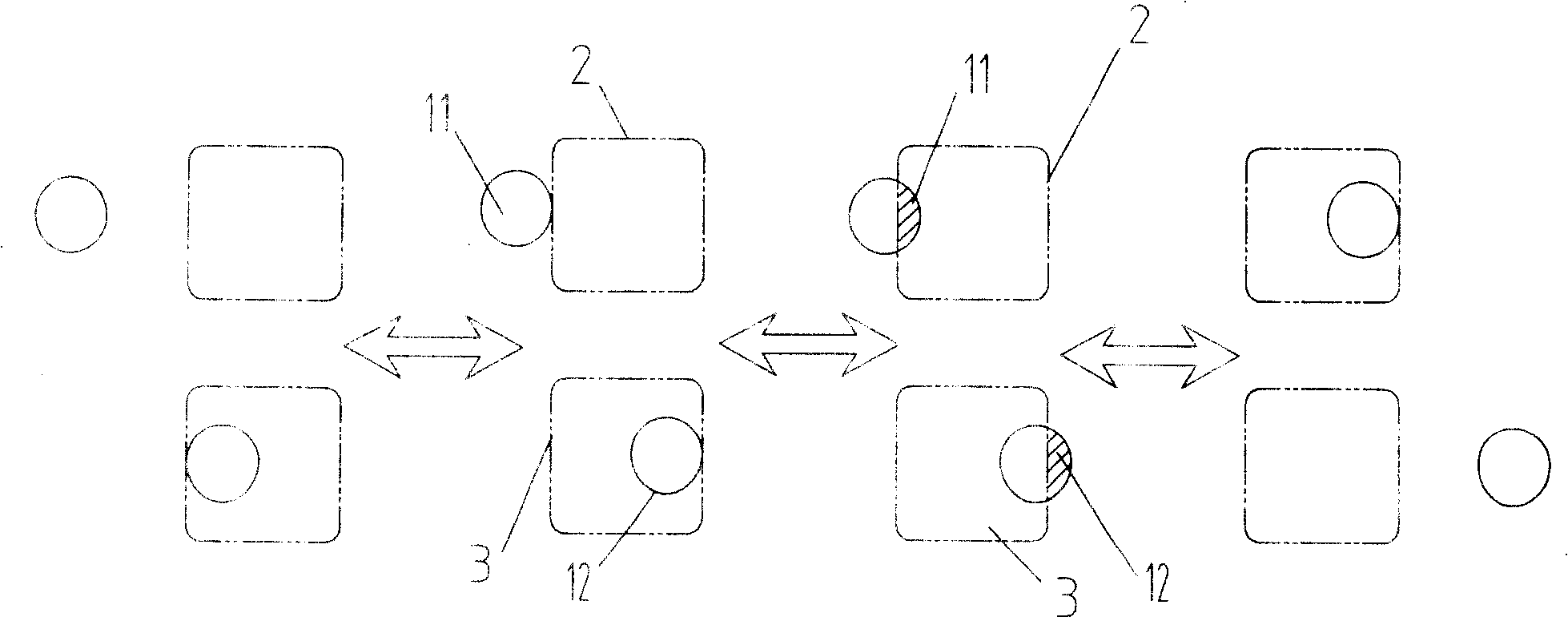
[0017] Wherein, the bottom of the cylindrical rotary valve core 7 communicates with the oil inlet hole 5 . An oil outlet hole 6 is opened on the passage where the inner cavity of the valve core 7 communicates with the oil inlet hole 5 . The cylinder body of the valve core 7 is provided with the same main oil hole 11 and oil drain hole 12 . A main working oil hole 2 is arranged on the valve body corresponding to the position of the main oil hole 11 on the outer side of the cylinder body of the valve core 7 . In use, the main working oil hole 2 is communicated with the main oil hole 11 by rotating the spool 7 to an appropriate position (such as image 3 and 4 Shown); On the valve body corresponding to the position of the drain hole 12 on the outside of the spool 7 cylinder, a working oil discharge hole 3 is arranged. In...


PUM


Abstract

A rotary switching valve is prepared as utilizing bottom opening to connect oil inlet hole to cylindrical rotary spool, setting master oil hole and oil discharge hole as both being in the same form on spool cylindrical body, connecting master oil hole through to master operation oil hole and oil discharge hole through to operation oil discharge hole by rotating spool and holding flow-area of spool to be constant in course of switching.

Description

technical field [0001] The invention relates to a switching valve, more specifically, to a two-position four-way electric switching valve used for a speed-regulating type hydraulic coupling supported by a sliding bearing or with externally supplied lubricating oil. Background technique [0002] In the speed-regulating fluid coupling supported by sliding bearings or with external lubricating oil, the lubrication method of the sliding bearings in the prior art is: take pressure oil for bearing lubrication before the oil inlet orifice of the fluid coupling . The problem with this oil circuit system is that before the hydraulic coupling is started, its working cavity has been filled with oil, so it is impossible to start the motor without load. For large inertia loads, it is very important to require the main motor to have no-load starting performance. For this reason, it is necessary for the switching valve to realize undisturbed switching, so as to ensure the stability of lu...

Claims


Application Information

Patent Timeline
Patent Type & Authority Patents(China)
IPC IPC(8): F16K11/085
Inventor 曹晓宁任小猛
Owner 大连创思福液力偶合器成套设备有限公司
Why Eureka
Try Eureka