
Overhead conveyor

A conveyor, suspended technology, applied in the field of suspended conveyors, can solve problems such as increasing the distance of the objects to be conveyed, reducing productivity, conflict or contact, etc.

Inactive Publication Date: 2008-08-20
NAKANISHI METAL WORKS CO LTD
View PDF8 Cites 6 Cited by
  • Summary
  • Abstract
  • Description
  • Claims
  • Application Information

AI Technical Summary

Problems solved by technology

Therefore, there is a problem that the objects conveyed by a certain carrier and hanger collide with or contact the objects conveyed by the carriers and hangers in front of or behind the carrier and hanger
In addition, in order to avoid such collision or contact, it is necessary to increase the distance between the conveyed objects, so the productivity is reduced

Method used


Image

  • Overhead conveyor
  • Overhead conveyor
  • Overhead conveyor

Examples


Embodiment Construction

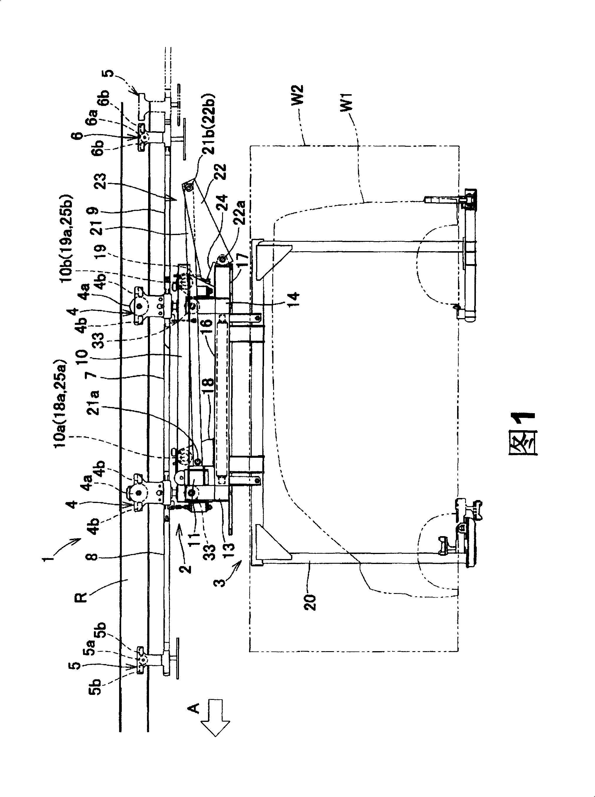
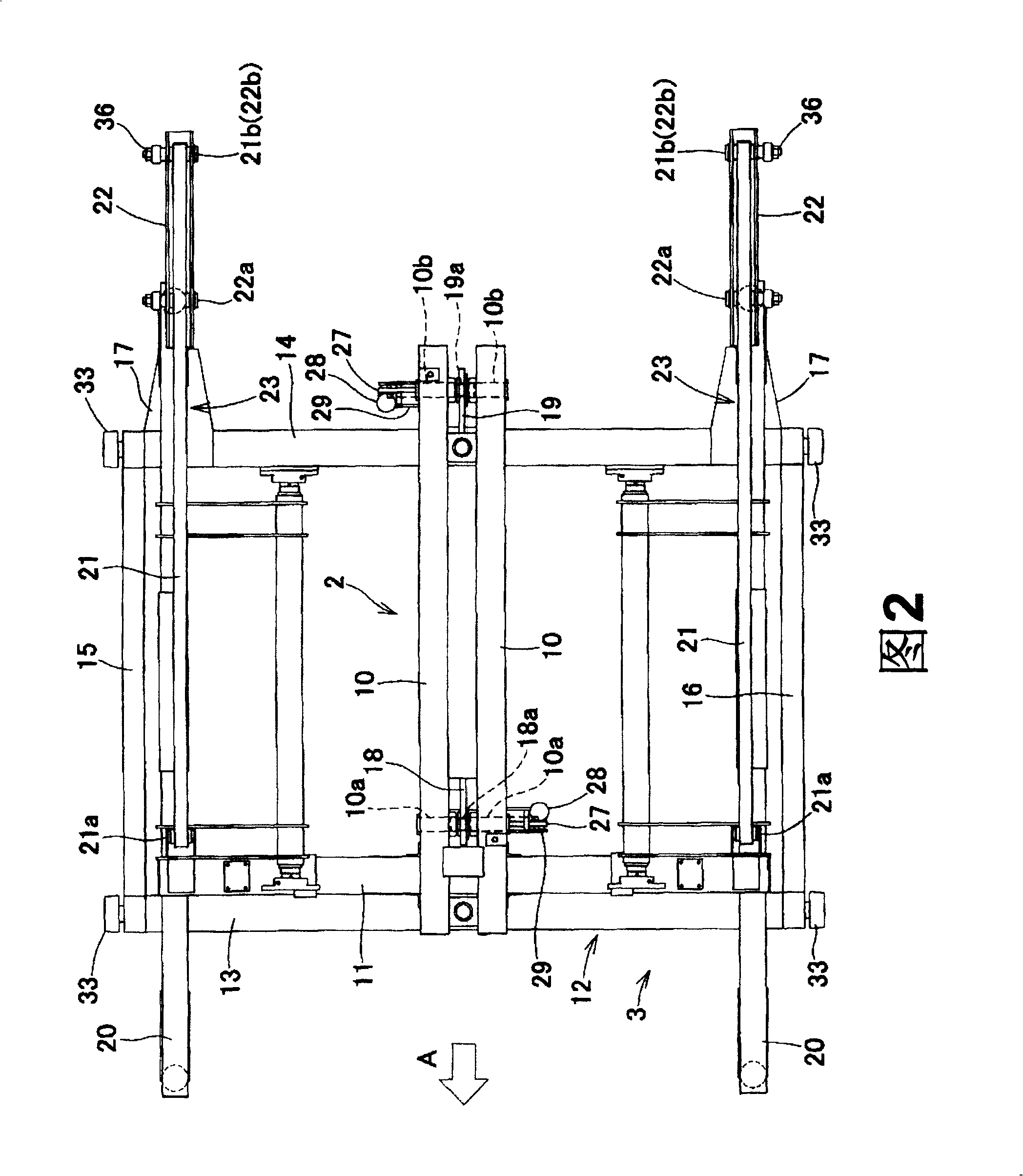
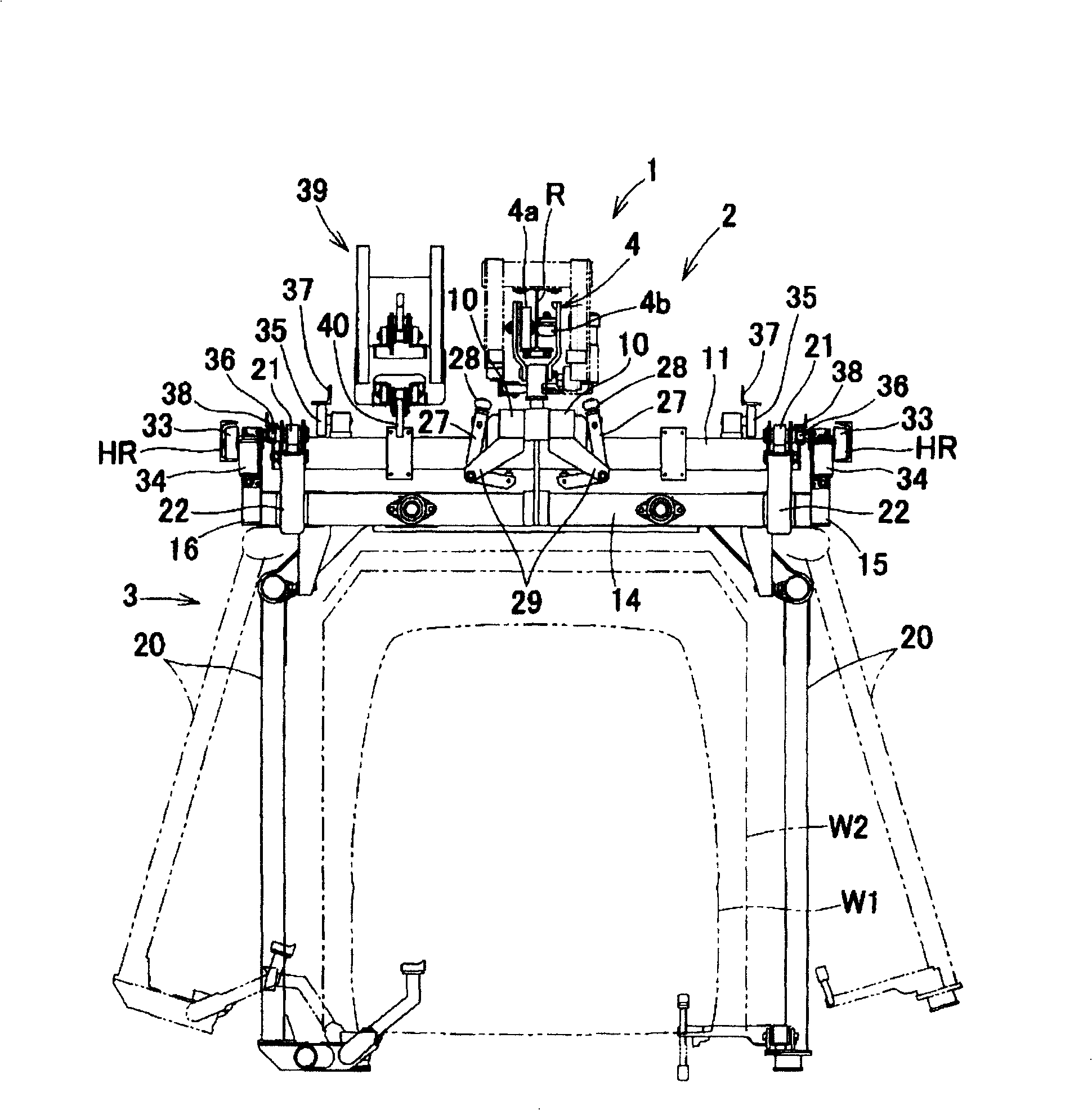
[0032] Next, embodiments of the present invention will be described in detail with reference to the drawings. However, the present invention is not limited to the embodiments shown in the drawings, and includes all embodiments satisfying the main content described in the claims. In this specification, the direction in which the carrier advances along the running track is defined as the front (see the direction of arrow A in the figure), the opposite side is defined as the rear, and the left and right sides of the carrier viewed from the front to the rear are defined as left and right.

[0033] Figure 1~ image 3 It is explanatory drawing which shows the overhead conveyor of embodiment of this invention. FIG. 1 is a right side view, and FIG. 2 is a plan view showing the underside of the trolley, image 3 It is a rear view (a view seen from the rear). Among them, in image 3 In , the trolley joined to the rail R represents a loading trolley (trolley) 4 . The overhead conveyor ...


PUM


Abstract

An overhead conveyor having a carrier (2) connected to front and rear trolleys (4, 4) engaging a travel rail (R), a hanger (3) capable of changing the state of its engagement with the carrier (2) and the state of release of the engagement, a tow bar (23) constructing an upper-lower swing three-joint link mechanism for connecting the carrier (2) and the hanger (3), and engagement / release switching means for switching between the engaged state and the released state. The engagement / release switching means enables switching between the engaged state where the hanger (3) moves with the carrier (2) in a united form and the released state where the hanger (3) is towed by the tow bar (23) while being supported by a hanger guiding rail (HR) provided under the travel rail (R). The height of an object to be conveyed can be changed to a height suitable for work.

Description

technical field [0001] The present invention relates to a machine that can be used in the same production line to carry out operations on conveyed objects of different sizes or shapes (for example, the operation of assembling a variety of automobiles on an automobile body assembly line). The hanger on the carrier is a suspended conveyor that conveys the conveyed objects. Background technique [0002] The suspended conveyor includes: a carrier with rollers that can rotate on a walking rail that is erected on the head of the operator (for example, close to the top of the workshop, etc.); object hanger. In addition, a power chain type drive device, a friction roller type drive device, or the like is used to drive the carrier. For example, when using such a suspended conveyor on an assembly line for assembling various automobile bodies, it must be configured so that the height of the conveyed object supported by the above-mentioned hanger can be changed to a height suitable fo...

Claims


Application Information

Patent Timeline
Patent Type & Authority Patents(China)
IPC IPC(8): B61B10/02B23P19/00B23P21/00B65G17/20B61B13/06B62D65/18
CPCB65G17/20B62D65/18B61B10/02B23P19/00B65G17/02
Inventor 佐伯泰纪小林幸彦古川隆之
Owner NAKANISHI METAL WORKS CO LTD
Learn More