Automatic KWH meter control system

A technology of automatic control system and electric meter, applied in electrical signal transmission systems, signal transmission systems, instruments, etc., can solve the problems of limited transmission power, large space electromagnetic wave interference, affecting transmission distance, etc., to achieve fast transmission speed and improve communication. The effect of speed and communication speed

Inactive Publication Date: 2008-08-06
李乐天
View PDF8 Cites 0 Cited by
  • Summary
  • Abstract
  • Description
  • Claims
  • Application Information

AI Technical Summary

Problems solved by technology

However, due to the large interference of space electromagnetic waves, especially the random obstruction of obstacles, the limited transmission power directly affects the transmission distance, so it is rarely used in China at present.

Method used


Image

  • Automatic KWH meter control system
  • Automatic KWH meter control system
  • Automatic KWH meter control system

Examples


Embodiment Construction

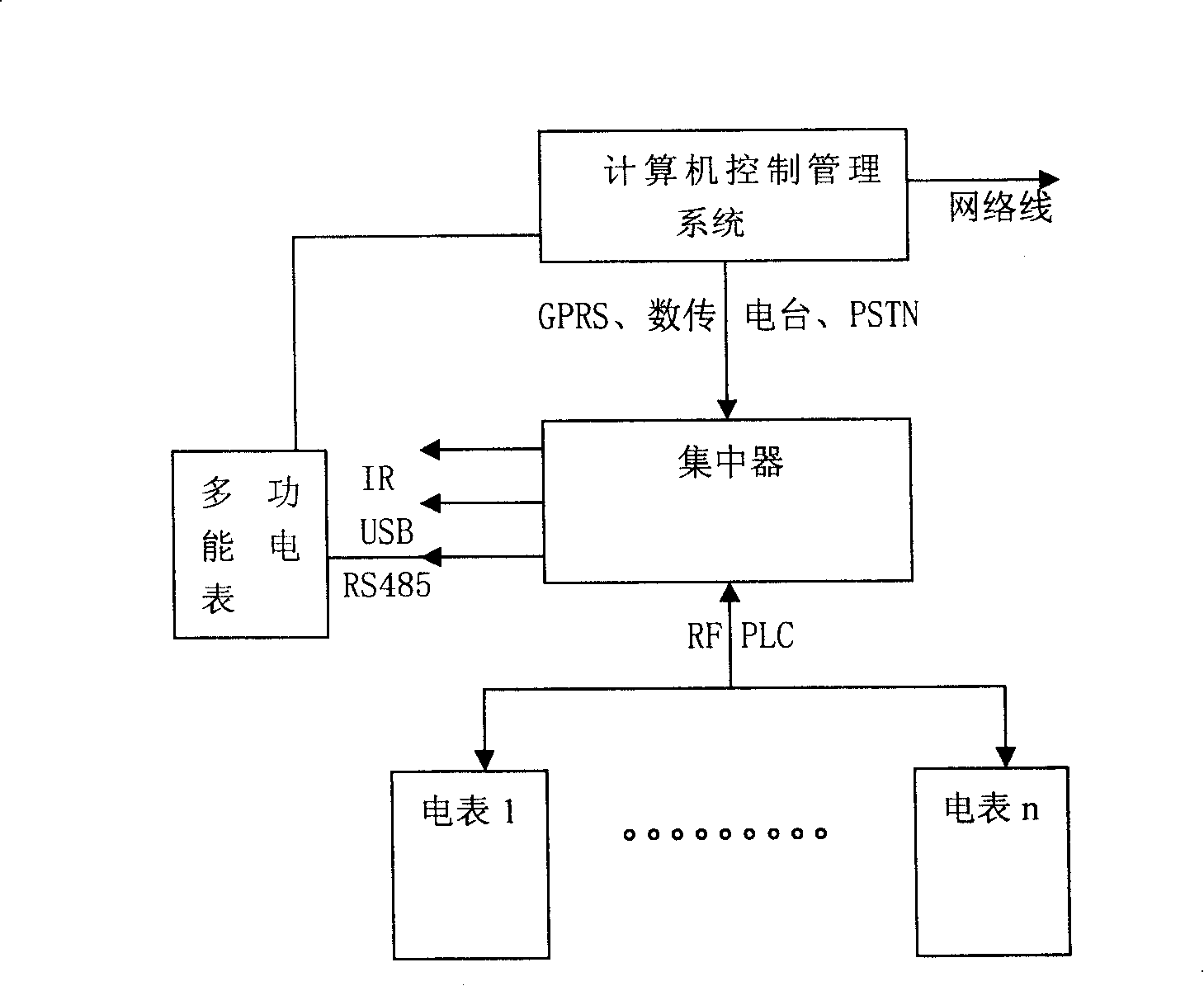
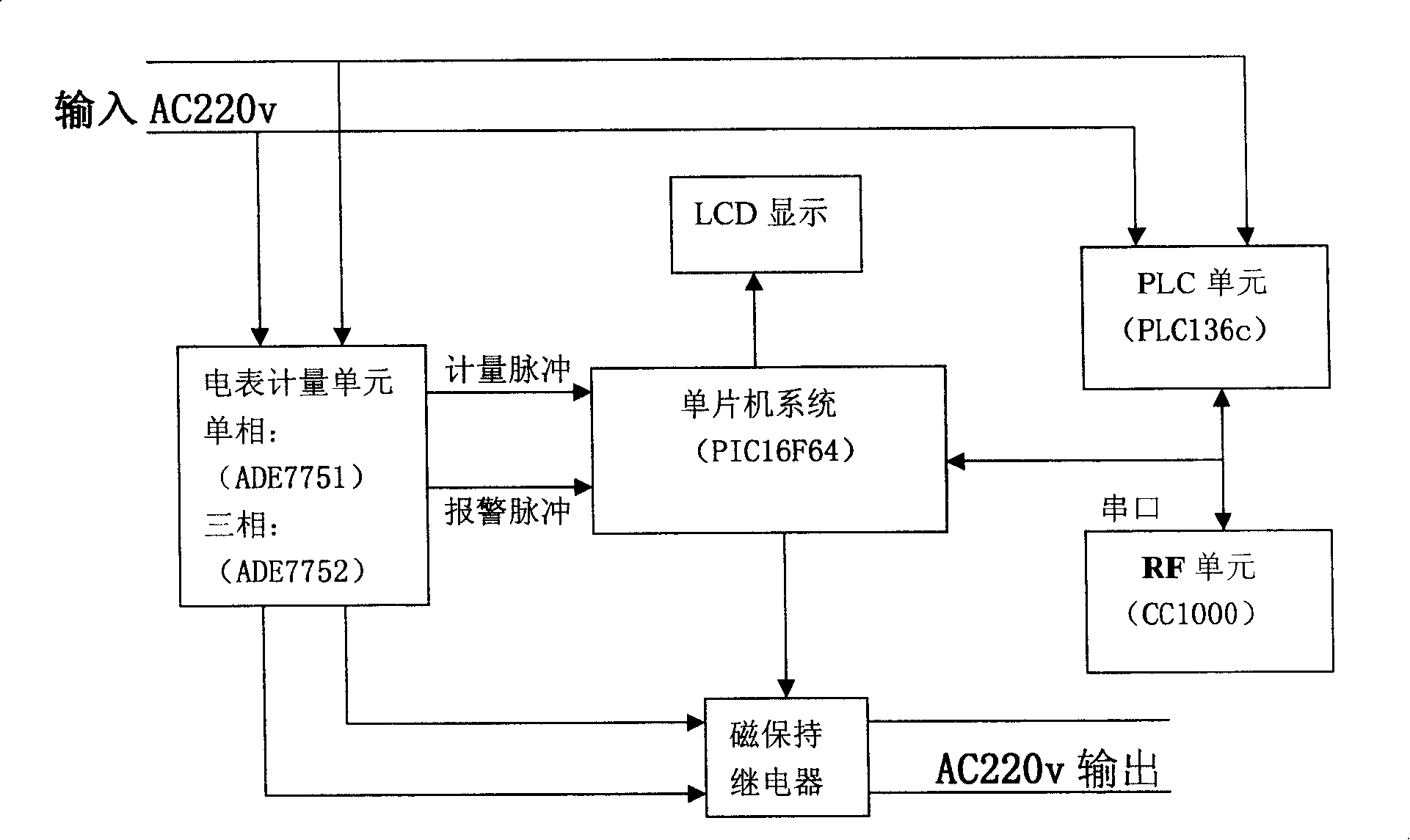
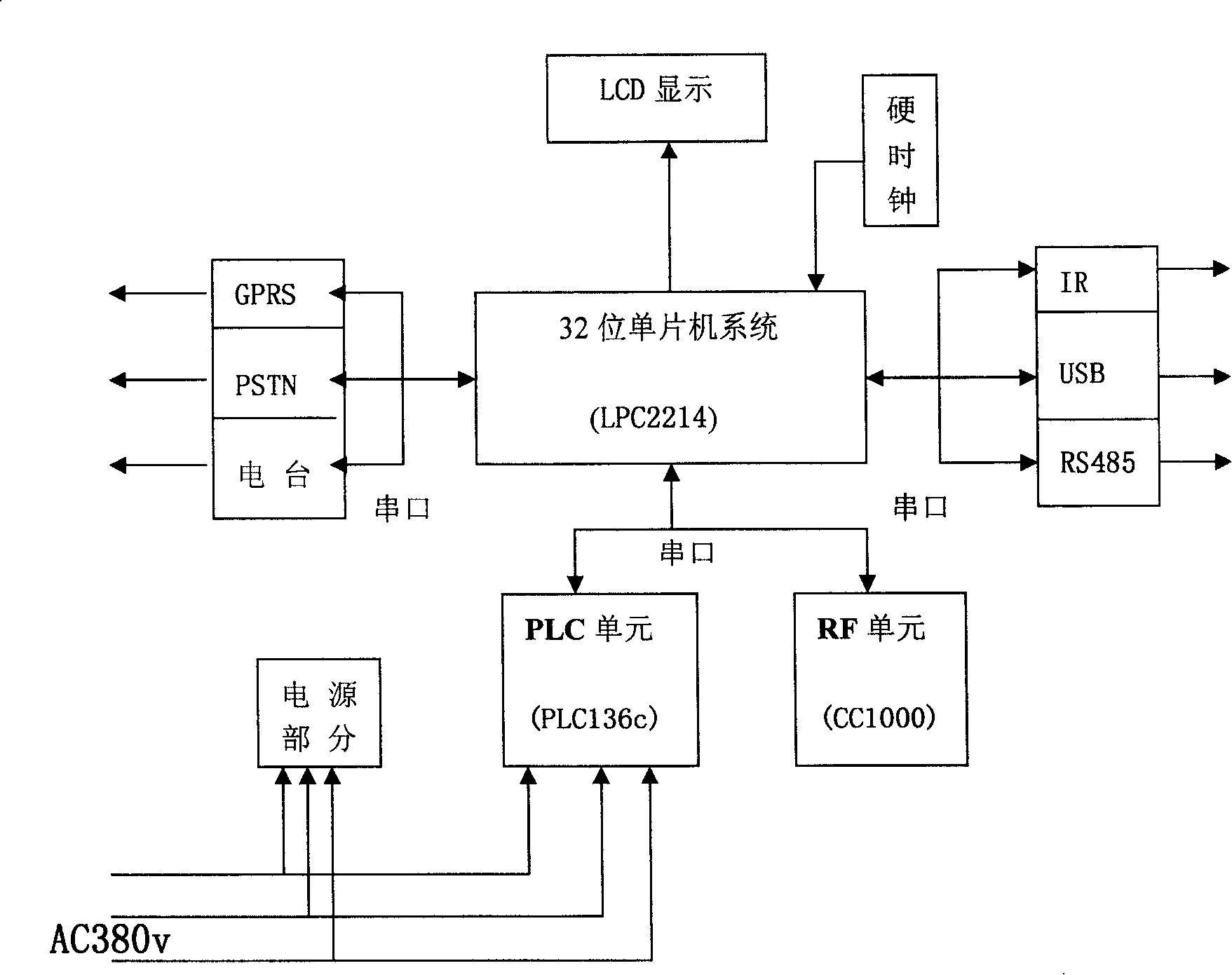
[0025] See attached figure 1, MACS in the figure includes computer control management system, concentrator and electric meter, wherein computer control management system includes computer system, GPRS and PSTN and data transmission station, network line; computer control management system through GPRS or PSTN or at least A connection concentrator through which meter data is received and control commands are sent. The concentrator includes single-chip microcomputer system, GPRS and PSTN and digital radio, IR and USB and RS485 interface, RF unit and PLC unit. The concentrator connects the meter through the RF unit and PLC unit, receives the meter data and sends control instructions; And RS485 is connected with the field equipment and the three-phase multi-function meter to receive the initialization data and send the data of the meter; the meter includes a metering unit, a magnetic latching relay, a single-chip microcomputer system, an RF unit, and a PLC unit.

[0026] See atta...


PUM


Abstract

The invention relates to an automatic control system for ammeter, which comprises: a computer control and management system, and some concentrators connected to some ammeters by means of RF and PLC. Wherein, connecting the computer system and concentrator by at least one means ob PSTN, digital-transmission radio station and GPRS; and connecting the ammeters each other by means of RF and PLC. This invention combines RF and PLC technique, builds a network platform for intelligent control, provides reliable criterion for electric inspection, and improves ammeter management level.

Description

Technical field [0001] The invention relates to an electric meter centralized management and automatic monitoring system, in particular to an electric meter automatic control system suitable for centralized management of electric meters in electric power systems. Background technique [0002] Electric meter management has always been a very troublesome matter that the power supply department is very concerned about. In the traditional meter reading charging and electricity monitoring, special personnel go to the user's site to read and check the meter, and the collected meter data is collected to the power supply department, and the power supply department issues tickets and charges according to relevant regulations. In this way, a large number of copying personnel are required, the labor intensity is high, the efficiency is low, and human errors may occur, resulting in some unnecessary social impacts, and at the same time affecting the corporate image of the power supply de...

Claims


Application Information

Patent Timeline
Patent Type & Authority Patents(China)
IPC IPC(8): G08C19/00G08C17/02
Inventor 李乐天
Owner 李乐天
Why Eureka
Try Eureka