Optical fibre with chromatic dispersion compensation

A dispersion compensating optical fiber and dispersion technology, which is applied to the required dispersion optical fiber, clad optical fiber, multi-layer core/clad optical fiber, etc., can solve the problems of ineffective compensation, low ratio of optical fiber dispersion and dispersion slope, etc.

Inactive Publication Date: 2008-05-21
DRAKA COMTEQ BV
View PDF8 Cites 0 Cited by
  • Summary
  • Abstract
  • Description
  • Claims
  • Application Information

AI Technical Summary

Problems solved by technology

[0004] For example, as described in patent application WO 01 / 01179, a first prior art solution employs a dispersion compensating fiber with a lower dispersion slope, however, the ratio of the dispersion to the dispersion slope of the fiber involved is too low and cannot effectively Compensation for NZ-DSF Transmission Line Fibers with Lower Dispersion Slope
[0005] In a second prior art solution presented at the OECC / IOOC'01 meeting, in a paper entitled "Dispersion flattened fiber with high negative dispersion", numerical simulations describe A dispersion compensating fiber with a very high ratio of dispersion to dispersion slope, however, those simulations presented orally at the same meeting did not confirm the above, but instead yielded usual values ​​including mode field diameters of the order of 4 μm

Method used


Image

  • Optical fibre with chromatic dispersion compensation
  • Optical fibre with chromatic dispersion compensation
  • Optical fibre with chromatic dispersion compensation

Examples


Embodiment Construction

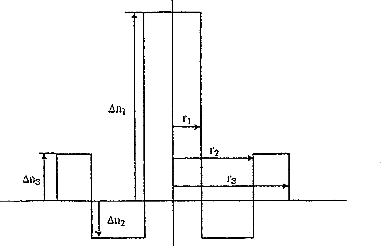
[0052] figure 1 An embodiment of a first type of profile having three layers of a dispersion compensating optical fiber according to the invention is schematically shown. The first layer, called the central layer, has a maximum refractive index difference Δn relative to the constant refractive index of the cladding 1 and the outer radius r 1 . The maximum refractive index difference Δn 1 is positive. The refractive index is preferably constant and is zero for radius with radius r 1 the maximum value between. The second layer, called the depressed layer, has a maximum refractive index difference Δn relative to the constant refractive index of the cladding 2 and the outer radius r 2 . The maximum refractive index difference Δn 2 is negative. The refractive index at radius r 1 with radius r 2 is preferably constant. The third layer, called the annular layer, has a maximum refractive index difference Δn relative to the constant refractive index of the cladding 3 and ...


PUM


Abstract

The invention relates to a multiband chromatic dispersion compensation optical fiber comprising successively, from the center toward the periphery, a central slice whose maximum index is higher than the index of the cladding, a buried slice whose minimum index is lower than the index of the cladding, and an annular slice whose maximum index is higher than the index of the cladding and lower than the maximum index of the central slice, a cladding of constant index, and having, on the one hand, at the wavelength of 1550 nm, firstly a chromatic dispersion of less than -8 ps/nm.km, secondly a chromatic dispersion to dispersion slope ratio whose absolute value is greater than 750 nm, and thirdly a mode diameter greater than 5 mum, and on the other hand, at the wavelength of 1625 nm, bending losses for a radius of 10 mm that are less than 400 dB/m.

Description

technical field [0001] The field of the invention is optical fibers for wavelength division multiplexed transmission networks. Background technique [0002] An increase in the bit rate of information on such a network imposes dispersion compensation and dispersion slope compensation over increasingly wider frequency bands. The S-band corresponds to a frequency band of about 1460 nm to 1530 nm. The C-band corresponds to a frequency band of about 1530 nm to 1565 nm. The L band corresponds to a frequency band of about 1565 nm to 1625 nm. The U-band corresponds to a frequency band of about 1625 nm to 1675 nm. The most widely used frequency band is the C-band. In addition to the C-band, it is increasingly desirable to use the C-band, S-band, L-band, or even the L-band. [0003] In the prior art, it is known to combine a dispersion-shifted fiber called a non-zero dispersion-shifted fiber (NZ-DSF) for reducing nonlinear crossover effects with a dispersion-compensating fiber (D...

Claims


Application Information

Patent Timeline
Patent Type & Authority Patents(China)
IPC IPC(8): G02B6/036G02B6/02
CPCG02B6/0228G02B6/02004G02B6/02261G02B6/03644G02B6/03627G02B6/0281G02B6/03666
Inventor 弗洛朗·博蒙皮埃尔·西拉尔德卢多维克·弗勒里马克西姆·戈尔利耶路易·阿内·德蒙莫里永帕斯卡莱·努希
Owner DRAKA COMTEQ BV
Why Eureka
Try Eureka