Circular spray type spray nozzle

A nozzle and ring spraying technology, applied in the direction of spraying device, spraying device, etc., to achieve the effect of improving spraying force, improving uniformity, and convenient structure setting

Inactive Publication Date: 2008-05-14
BAODING TIANWEI ELECTRICAL EQUIP STRUCTURE
View PDF4 Cites 0 Cited by
  • Summary
  • Abstract
  • Description
  • Claims
  • Application Information

AI Technical Summary

Problems solved by technology

[0003] The technical problem to be solved by the present invention is to provide a ring spray nozzle that can spray 360° all around the nozzle, so as to overcome the defects and limitations of the existing direct injection nozzle

Method used


Image

  • Circular spray type spray nozzle

Examples


Embodiment Construction

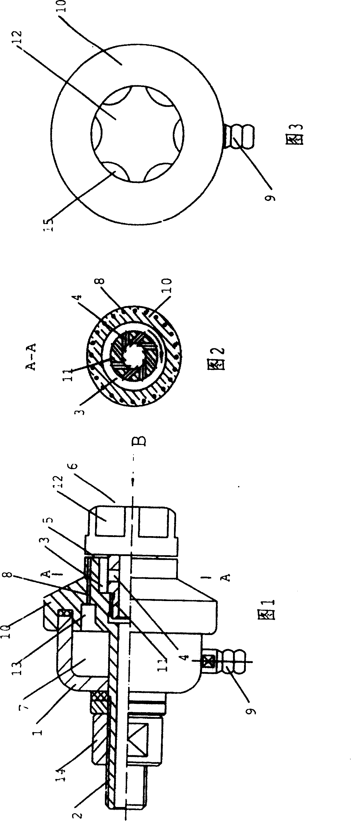
[0022] See attached picture. The annular nozzle 5 in the present invention is an annular gap located at the front end of the nozzle body, and the annular gap is perpendicular to the axis of the nozzle body, that is, perpendicular to the traveling direction of the gas. The liquid inlets 8 are distributed on the side wall of the annular gap forming the annular spout 5 . The pressurized gas travels straight forward in the nozzle body to the annular nozzle 5. When it suddenly turns 90° and changes the line, it is sprayed out in a 360° direction around the nozzle. The local negative pressure during injection will suck the liquid in the liquid inlet 8 into the gas. Form a gas-liquid mixture and spray it out.

[0023] Still refer to the accompanying drawings. The nozzle body in the present invention can adopt the structural form in which the intake pipe 2 is arranged in the casing 1 and a vortex generator is arranged at the front end of the intake pipe 2 . The annular air chamber ...


PUM


Abstract

This invention relates to a circular blow head, which belongs to the blow head technology field. The blow head comprises the blow head body, air-in port, liquor-in port and ejector nozzle, wherein the ejector nozzle is ring, formed by the ring gap vertical to the axle of the blow head body; the liquor-in port is set in the lateral wall of the ring ejector nozzle. The ring form ejector nozzle is vertical to the air walking direction, which makes the concurrent gas-liquid flow ejecting omnibearingly; in addition, the differential pressure before and after ejecting is big, which can enforce the association probability of the droplet and high-temperature vessel, air, and dust-laden air. The invention can be used as the tool for cooling, cleaning and spraying protective coating.

Description

technical field [0001] The invention relates to a liquid atomizing device and belongs to the technical field of nozzles. Background technique [0002] The nozzle has a nozzle body, an air inlet, a liquid port and the like. When working, when the pressure gas is sprayed out through a small nozzle, a local negative pressure is formed around the nozzle, and the medium surrounding the nozzle is sucked into the gas under the action of negative pressure, and the gas-liquid mixture drops sharply after being sprayed out. It expands to form mist droplets, so as to realize its functional requirements as a component for spraying cooling and spraying protective coatings. The existing nozzle is in the form of direct injection structure. When spraying, the gas-liquid mixture is directly injected forward from the nozzle, and the injection direction is parallel to the direction of pressure gas travel. The angle is generally less than 90°, which can only cover a small area in front of the ...

Claims


Application Information

Patent Timeline
Patent Type & Authority Patents(China)
IPC IPC(8): B05B1/34
Inventor 项新友孟庆彪马四龙
Owner BAODING TIANWEI ELECTRICAL EQUIP STRUCTURE
Why Eureka
Try Eureka