Terminal structure of extreme-low temperature equipment
A technology for low-temperature equipment and terminal structure, which is applied to cable accessories, cable terminals, and equipment for connecting/terminating cables of low-temperature cables, etc., and can solve problems such as mechanical damage, high pressure, and deterioration of insulation performance.
- Summary
- Abstract
- Description
- Claims
- Application Information
AI Technical Summary
Problems solved by technology
Method used
Image
Examples
no. 1 example
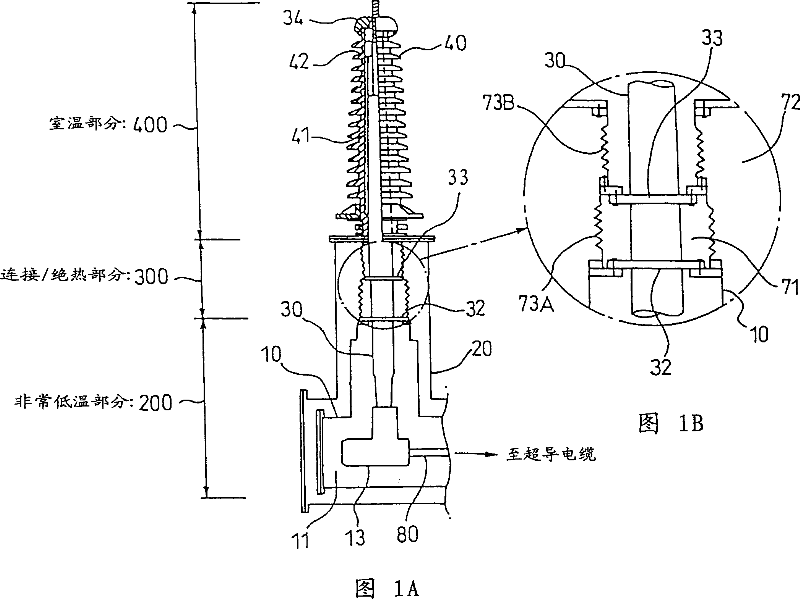
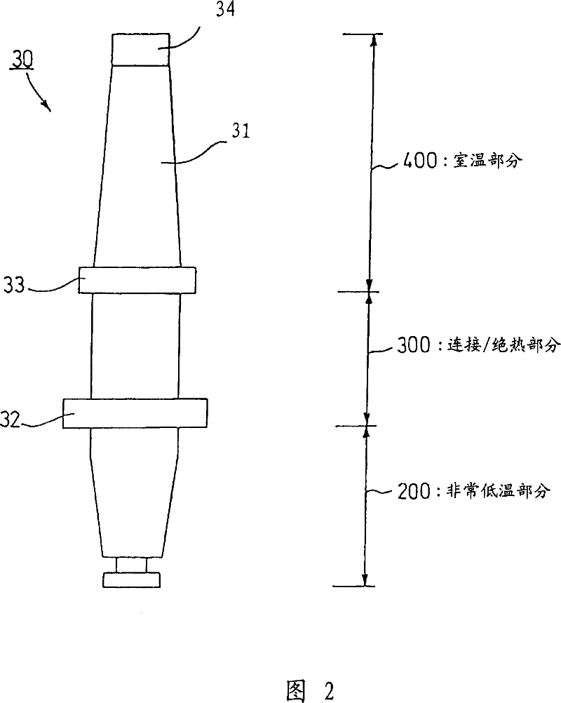
[0087] Now, the terminal structure of the superconducting cable will be described by way of example. FIG. 1 is a schematic diagram of a terminal structure according to the present invention. This terminal structure has: a very low temperature part immersed in the liquid nitrogen 11 in the cryogen tank 10; a room temperature part 400 placed in the insulator 40; and a connection / connection formed between the very low temperature part 200 and the room temperature part 400 Insulation portion 300.
[0088] The vacuum vessel 20 is connected to a heat insulating tube (not shown) of the superconducting cable. A vacuum is maintained in the vacuum vessel 20 at the portion connected to the heat insulating tube and in the heat insulating tube. In this embodiment, the opening diameter of the vacuum vessel 20 is set to φ600 mm.
[0089] The connecting conductor 80 , which is connected to the insulator 40 of the superconducting cable, leads into the cryogen tank 10 . The cryogen tank 10 ...
no. 2 example
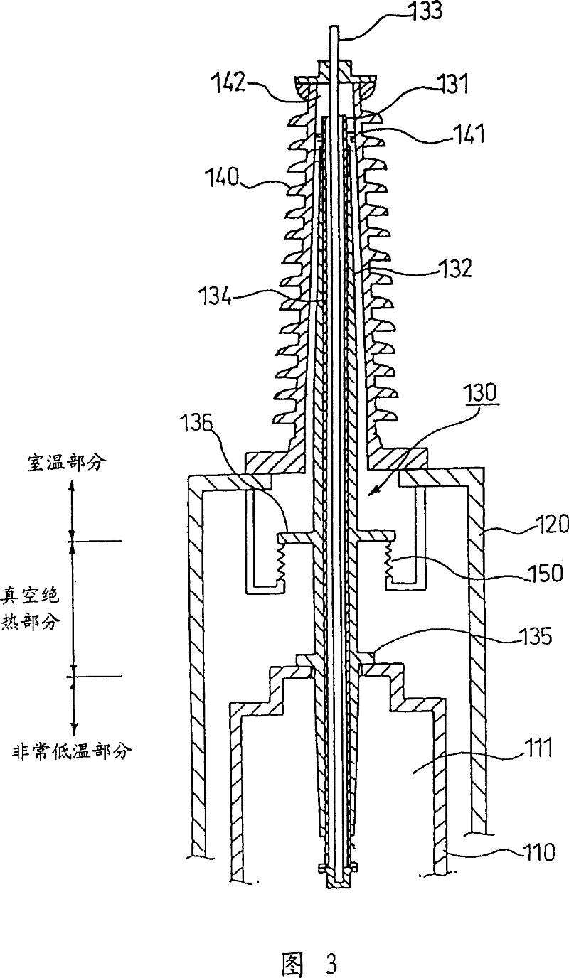
[0106] Now, the terminal structure of the superconducting cable will be explained with the help of an example. Fig. 3 is a schematic diagram of a terminal structure according to the present invention. The terminal structure has: a very low temperature part 200 immersed in liquid nitrogen 111 in a cryogen tank 110; a room temperature part 400 placed in an insulator 140; and a connection / connection formed between the very low temperature part and the room temperature part Insulation portion 300.
[0107] A connection conductor connected to a conductor of a superconducting cable, not shown, leads through the vacuum vessel 120 into the cryogen tank 110 forming part of the cryogenic section 200 . The cryogen tank 110 is a cylindrical tube into which liquid nitrogen 111 is hermetically filled. In the refrigerant tank, the above-mentioned connection conductor is connected to the sleeve 130 (conductor portion).
[0108] The cryogen tank 110 of this structure is placed in the vacuum...
no. 3 example
[0119] Fig. 4 shows an example in which the structure of the room temperature part is different. The structure of the third embodiment is the same as that of the first embodiment except that the structure of the end portion of the room temperature portion is different. Therefore, differences will be mainly described.
[0120] The structure of the room temperature part is that the sleeve 130 is placed in the insulator, but the space 134 formed in the sleeve 130 does not communicate with the air gap part 142 formed above the insulating oil container. In this case, a vacuum is created in the space inside the sleeve, or the space inside the sleeve is filled with helium gas that does not liquefy at extremely low temperatures. The space inside the sleeve is sealed by welding the end of the stainless steel pipe 131 or the like. With this structure, liquefaction of the substance inside the sleeve can be prevented, so that an excessive pressure change in the sleeve can be suppressed....
PUM
 Abstract
Description
Claims
Application Information
 - R&D
- Intellectual Property
- Life Sciences
- Materials
- Tech Scout
- Unparalleled Data Quality
- Higher Quality Content
- 60% Fewer Hallucinations
Browse by: Latest US Patents, China's latest patents, Technical Efficacy Thesaurus, Application Domain, Technology Topic, Popular Technical Reports.
© 2025 PatSnap. All rights reserved.Legal|Privacy policy|Modern Slavery Act Transparency Statement|Sitemap|About US| Contact US: help@patsnap.com


