
Truss type rigidifying solar energy cell array of inflatable expansion

A solar cell array, inflatable deployment technology, applied in the field of solar cell arrays, can solve the problems of difficult attitude control of solar cell arrays, reduced structural rigidity and fundamental frequency, poor deployment reliability, etc., and achieves high deployment reliability, heavy overall weight, Easy to fold effect

Inactive Publication Date: 2007-10-31
HARBIN INST OF TECH
View PDF5 Cites 0 Cited by
  • Summary
  • Abstract
  • Description
  • Claims
  • Application Information

AI Technical Summary

Problems solved by technology

[0003] The purpose of the present invention is to solve the problems of complex structure, easy failure, poor deployment reliability, heavy overall weight and low folding efficiency in use of the traditional unfolded solar cell array using a mechanical rigid structure, and the use of a large-area plane The structure stiffness and fundamental frequency decrease with the increase of the structure size in the frame-type deployment structure, which is easy to cause resonance with the main body of the satellite, and it is difficult to control the attitude of the solar cell array. A truss-type solar cell array that can be rigidized and inflated is provided.
2. Since the present invention adopts a truss-type solar cell array that can be rigidized and inflated to expand, it solves the problem that the traditional deployable solar cell array adopts a mechanical rigid structure, which has complex structures, easy failures, poor deployment reliability, and overall weight in use. The problem of heavy weight and low folding efficiency and the solar cell array adopting a large-area planar frame-type unfolded structure have structural stiffness and fundamental frequency that decrease with the increase of the structure size, which is easy to cause resonance with the main body of the satellite, and it is difficult to control the attitude of the solar cell array The problem

Method used


Image

  • Truss type rigidifying solar energy cell array of inflatable expansion
  • Truss type rigidifying solar energy cell array of inflatable expansion
  • Truss type rigidifying solar energy cell array of inflatable expansion

Examples


specific Embodiment approach 1

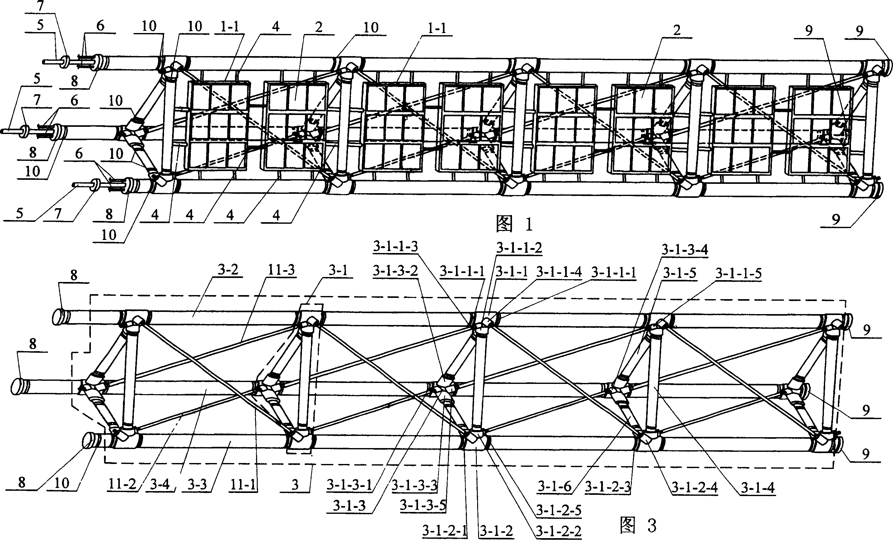
[0006] Specific Embodiment 1: This embodiment is described in conjunction with Fig. 1, Fig. 3, Fig. 5, Fig. 9, and Fig. 11. Pipeline 5, wire 6, control valve 7, inflatable terminal plate 8, connecting plate 9, and clamp 10; the truss 3 is composed of a group of truss units connected end to end and fixed with clamp 10, the same plane of each truss unit A substrate is placed inside, and the substrate and the truss unit are fixedly connected by a tie 4. The upper end of the substrate has a solar panel 2, the head end of the truss 3 is fixedly connected to the inflatable terminal plate 8, and one end of the wire 6 passes through the inflatable terminal plate 8. It is connected with the electric heating layer 3-6 on the main support pipe, and one end of the inflatable pipe 5 is installed in the main support pipe through the inflatable terminal plate 8, and the control valve 7 is installed on the inflatable pipe 5, and the tail end of the truss 3 is fixed with the connection plate 9 ...

specific Embodiment approach 2

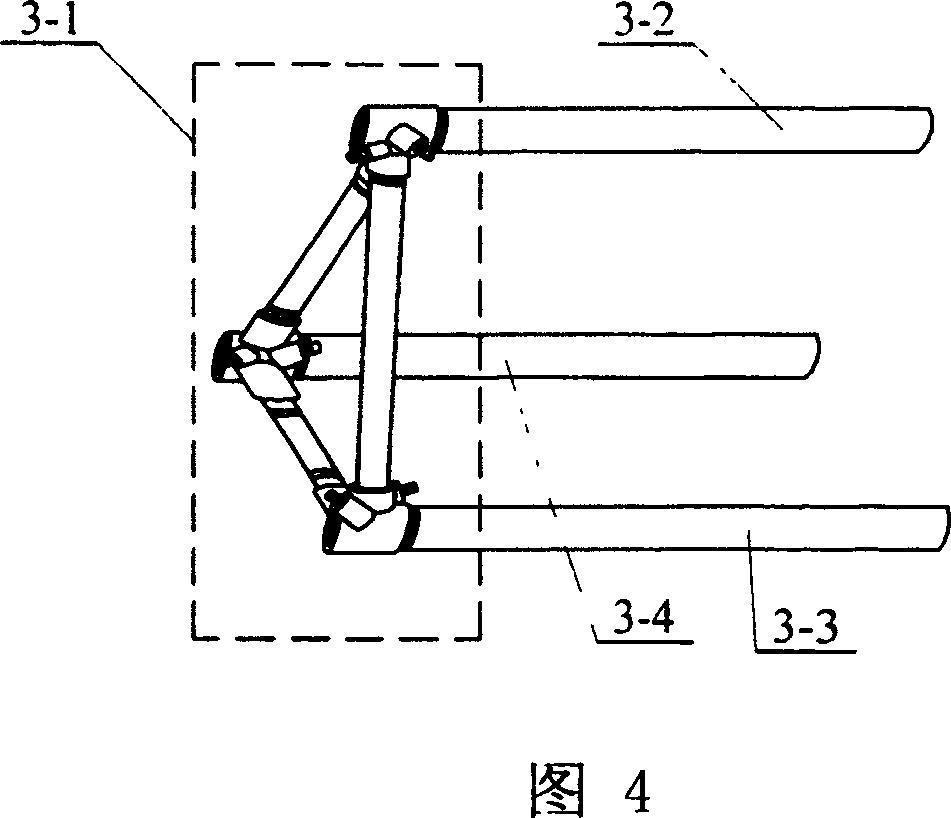
[0010] Specific embodiment two: this embodiment is described in conjunction with Fig. 3, the truss unit of this embodiment is made up of triangular support frame 3-1 and main support tube; Described main support tube is made up of first main support tube 3-2, second The main support pipe 3-3 and the third main support pipe 3-4 are composed; the tail end of the first main support pipe 3-2 is installed on the first six-way connecting pipe fitting 3-1-1 in the triangular support frame 3-1 The pipe wall of the main pipe joint 3-1-1-1 is fixedly connected by the clamp 10, and the tail end of the second main support pipe 3-3 is installed on the second six-way connecting pipe fitting 3 in the triangular support frame 3-1 - The pipe wall of the main pipe joint 3-1-2-1 on the -1-2 is fixedly connected by a clamp 10, and the tail end of the third main support pipe 3-4 is mounted on the third part of the triangular support frame 3-1. The six-way connection is on the pipe wall of the main...

specific Embodiment approach 3

[0011] Specific embodiment three: This embodiment is described in conjunction with Fig. 3 and Fig. 12. The triangular support frame 3-1 of this embodiment is composed of a secondary support pipe and a six-way connecting pipe; the six-way connecting pipe is connected by the first six-way The pipe fitting 3-1-1, the second six-way connecting pipe fitting 3-1-2, and the third six-way connecting pipe fitting 3-1-3; the auxiliary supporting pipe is composed of the vertical pipe 3-1-4, the first inclined Pipe 3-1-5, the second inclined pipe 3-1-6; the first six-way connection pipe fitting 3-1-1 and the second six-way connection pipe fitting 3-1-2 are placed symmetrically up and down, and the third six-way connection The pipe fitting 3-1-3 is placed directly behind the first six-way connecting pipe fitting 3-1-1 and the second six-way connecting pipe fitting 3-1-2, and the vertical pipe on the first six-way connecting pipe fitting 3-1-1 The joint 3-1-1-2 is fixedly connected to one e...


PUM


Abstract

Disclosed a girder-like solar energy battery array which can spread via aeration relates to a solar battery array used in the spacecraft. The invention can solve the problems of traditional folding solar battery array which uses the mechanical rigid structure, with complex structure, worse folding reliability and lower folding efficiency; and the problems of large-scale plat frame folding structure as the reduction of structural rigidity and basic frequency with the increase of size. Wherein, the girder (3) is formed by the connection between a group of girder units, while the same planes of each girder unit have basic plates to be fixed via the belt; the upper end surface of basic plate has a solar battery panel (2); the initial end of girder (3) is connected to the connection disc (8) of aeration end; one end of wire (6) is connected to the electric heating layer (3-6) of main supporting tube; one end of aeration tube (5) is inside the main supporting tube which has a control valve (7); and the tail end of girder (3) is connected to the connection disc (9).

Description

technical field [0001] The invention relates to an expandable solar battery array used on space vehicles such as satellites or manned spacecraft, in particular to a truss-type solar battery array that can be rigidized and inflated to expand. Background technique [0002] Solar cell array is the main form of power supply for space vehicles such as satellites, and has been widely used in space vehicles such as satellites, manned spacecraft, and space stations. The development of modern aircraft technology requires larger and larger solar cell arrays to provide higher energy power supply. The traditional deployable solar cell array mainly adopts a mechanical rigid structure. This deployable support structure is composed of many rigid components connected through a connecting mechanism, a control deploying mechanism and a locking mechanism. In use, there are complex structures, easy failures, and deployment Poor reliability, heavy overall weight, and low folding efficiency (suc...

Claims


Application Information

Patent Timeline
Patent Type & Authority Patents(China)
IPC IPC(8): B64G1/44H01L31/045
CPCY02E10/50
Inventor 苗常青谢志民刘宇艳谭惠丰
Owner HARBIN INST OF TECH
Learn More