Dust filter for using in operations endangered by gases

A dust filter and dangerous technology, applied in the field of dry dust filter, can solve the problems of unmentioned solutions, and achieve the effect of reducing ignition and preventing electrostatic charging

Inactive Publication Date: 2007-09-19
CFT GMBH
View PDF2 Cites 0 Cited by
  • Summary
  • Abstract
  • Description
  • Claims
  • Application Information

AI Technical Summary

Problems solved by technology

which does not mention the scheme of use in gas work and the avoidance of charging

Method used


Image

  • Dust filter for using in operations endangered by gases
  • Dust filter for using in operations endangered by gases
  • Dust filter for using in operations endangered by gases

Examples


Embodiment Construction

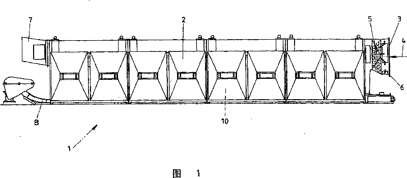
[0030] Figure 1 is a side view of a dry dust filter 1 assembled from individual elements. The assembled unit can be placed in the ground or also suspended from a monorail or other structure via the hooks visible above. The housings 2 of all these individual units are identical, with the filter inlet 3 having a coarse filter 5 for pre-dust removal, ie here the coarser fraction is separated from the air flow passing through. The direction of flow is indicated by 4 .

[0031] The filter inlet 3 has a connecting flange 6 which can be connected to a pre-separator which will be described in more detail below.

[0032] The filter outlet 7 forms the rear end of the housing 2, of which the shown dust filter 1 shows only one possibility. In the case of the housing 2 shown here, the cleaned wind flow exits at the filter outlet 7 . A plurality of filter elements 10 are arranged in the housing 2 . The filter elements are cleaned at regular intervals, the dust falling here falling into ...


PUM


Abstract

The invention relates to a dust filter unit (1) for condition containing dangerous gases, which includes filter element (10). The filter element (10) is antistatic by deduced components of carbon fibers, salts, or special steel fibers (26, 27), wherein, the filter element (10) connects to shell frame (14) by conductor (16) sorrounding sealing element (15) to avoid the charge in internal space of single filter element (10) or dust filter unit (1).

Description

technical field [0001] The invention relates to a dry dust filter for use in gas-hazardous working conditions, especially underground mining or construction tunnels, which has a housing in which one or more dust-absorbing and dust-containing air streams are arranged. A filter element having a dust-suppressing filter material and / or being designed accordingly. Background technique [0002] Such dust filters, ie, filter driers, are used in various fields of industry in order to settle the dust generated during mining or production processes as early and extensively as possible and thereby separate it from the air or wind current. In this case, a filter element made of filter cloth or a corresponding knitted fabric or similar material is arranged in a housing usually made of metal, which is passed through by an air flow or wind flow, wherein the filter element traps the passing dust so that Correspondingly cleaned air or wind flows out on the outlet side of the housing. [00...

Claims


Application Information

Patent Timeline
Patent Type & Authority Patents(China)
IPC IPC(8): B01D46/42B01D46/10B01D46/24B01D46/00
CPCB01D46/0093B01D46/0035B01D46/24B01D46/003B01D46/2403B01D46/4209B01D45/08B01D50/20
Inventor R·博特
Owner CFT GMBH
Why Eureka
Try Eureka