Double shell dispenser

Inactive Publication Date: 2007-07-17
BERRY PLASTICS CORP
View PDF19 Cites 12 Cited by
  • Summary
  • Abstract
  • Description
  • Claims
  • Application Information

AI Technical Summary

Benefits of technology

[0006]It is another object of the present invention to provide a double shell dispenser closure having a stopping mechanism which limits the range of rotation of a closure cap about a container finish.

Problems solved by technology

The cap of this type of closure commonly has a limited range of rotation, so that the cap may remain affixed to the container even while in the open position.

Method used


Image

  • Double shell dispenser
  • Double shell dispenser
  • Double shell dispenser

Examples


Embodiment Construction

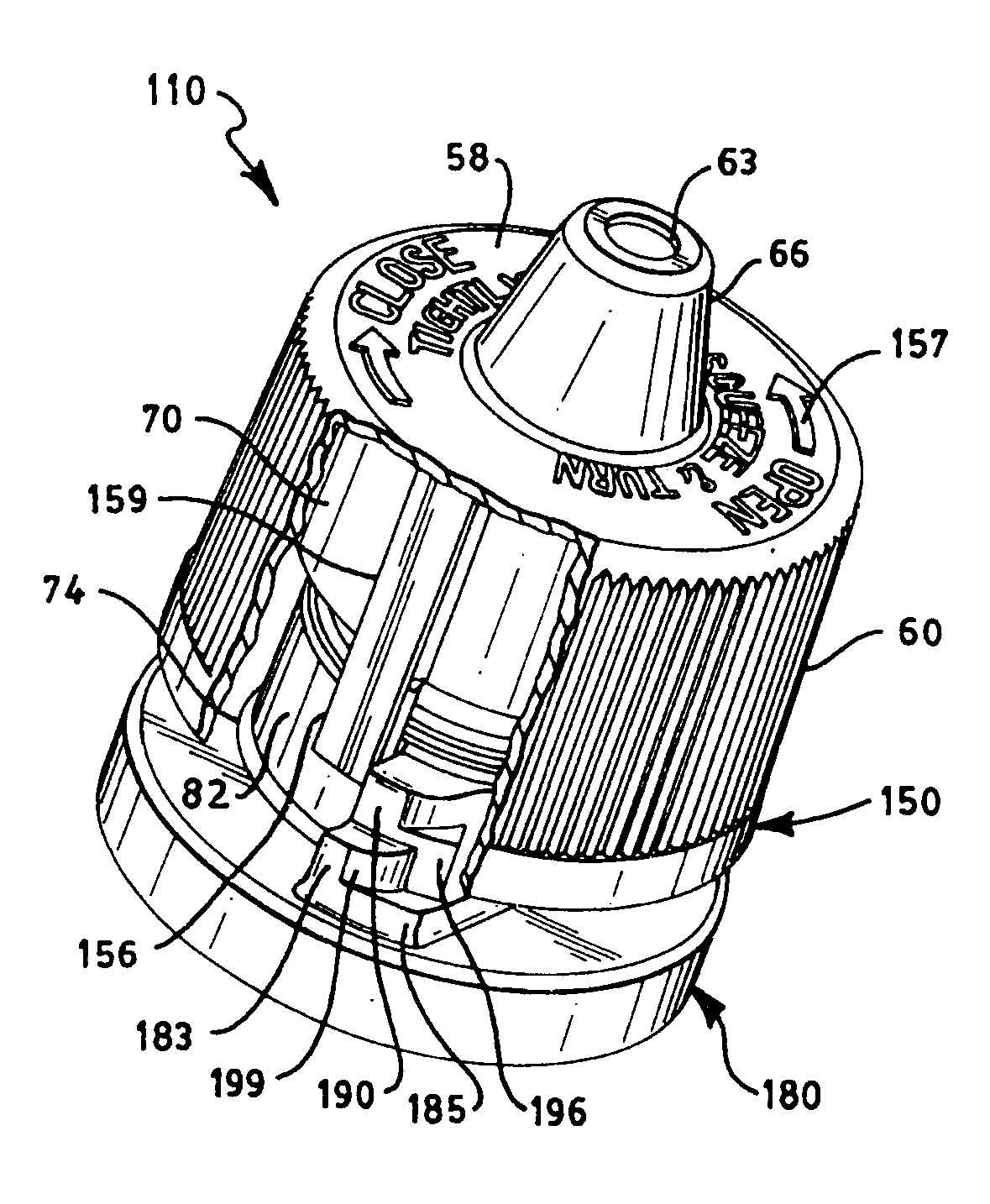
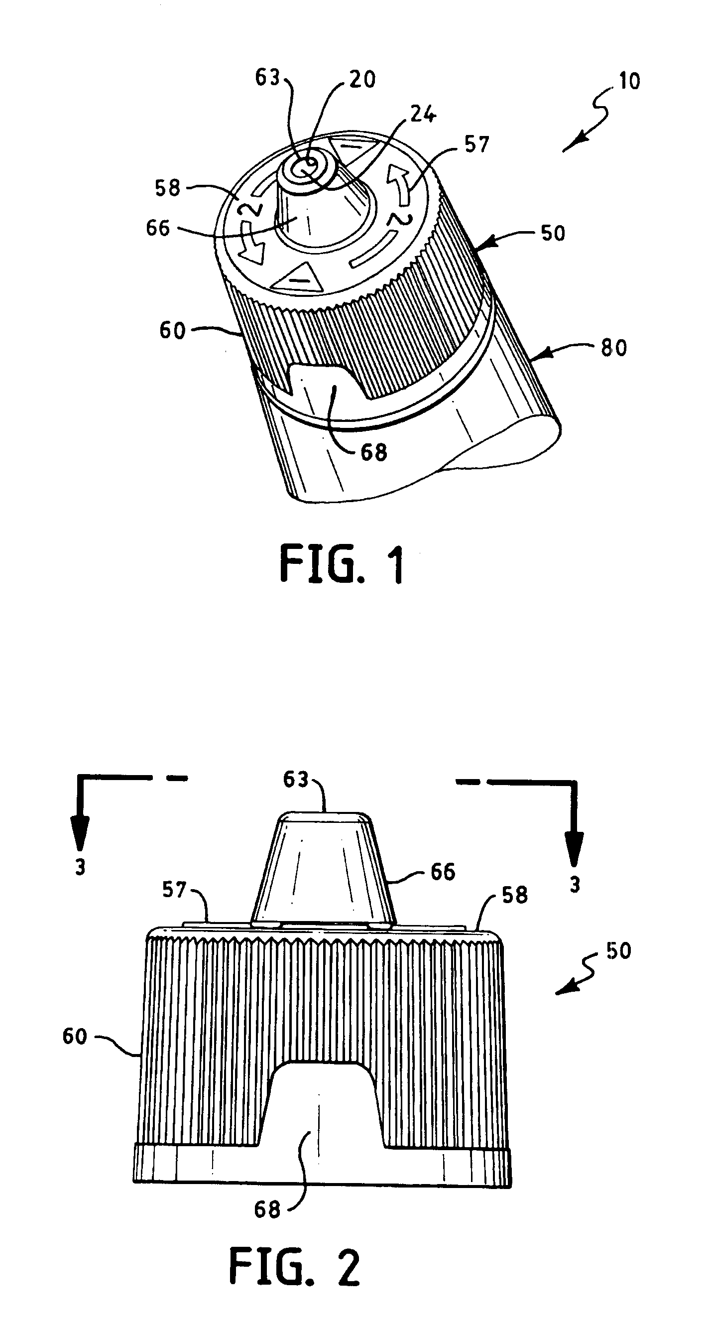
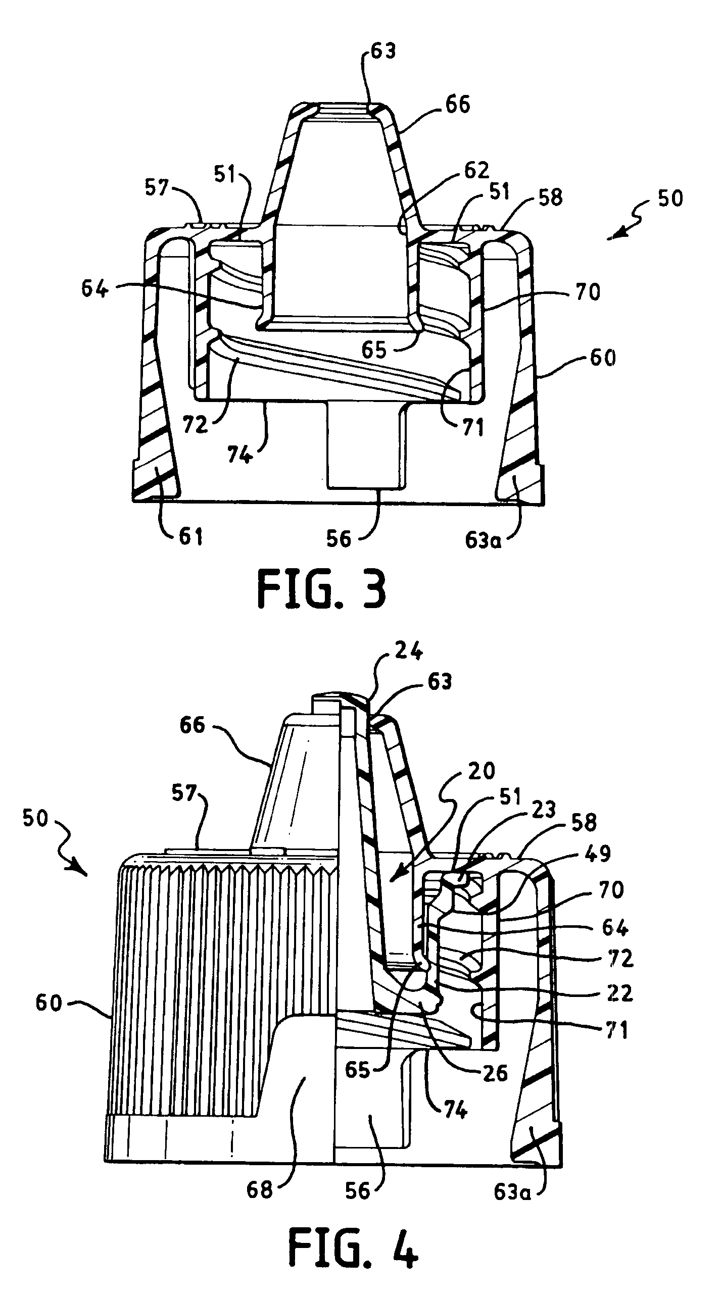
[0022]As shown in the FIGS. 1-13, a closure of the present invention is provided having a dispensing feature with a stopping mechanism which facilitates the dispensing of the contents of a tube, bottle or similar container, but prevents removal of the closure from the container. Closure 10 may be formed of any material well known in the art, such as polypropylene and polyethylene. As shown in FIG. 1, the closure 10 includes a cap body 50, a fitment 20 and a container finish 80. The cap body 50 is threadably attached to the container finish 80, so that the cap body 50 may threadably rotate axially along the neck portion 82 of the container finish 80. In this manner, the cap body 50 may be rotated from a closed position to an open position in order to access the contents of the container (not shown) upon which the container finish 80 is disposed. The fitment 20 is positioned within closure 10 so that the opening 63 in the spout portion 66 of the cap body 50 is sealed by the post 24 of...


PUM


Abstract

A dispenser closure is provided having a stopping mechanism that limits the rotation of the closure and generally prevents removal of the closure cap from the container. The dispenser closure includes a cap body, fitment and container finish. The cap body has a double shell design, which includes at least one drop lug projecting from the inner shell. When the cap body is rotated about the container finish, the drop lug engages at least one lug stop located on the container finish so as to limit the rotation, thereby preventing removal of the cap body from the container finish.

Description

BACKGROUND OF THE INVENTION[0001]1. Field of the Invention[0002]The present invention relates generally to dispenser closures. More particularly, the present invention relates to threadably movable dispenser closures with stopping mechanisms.[0003]2. Discussion of the Prior Art[0004]Dispenser closures that open by the axial movement of a cap along a container finish are generally known in the art. Such a closure commonly includes a cap portion that is threadably attached to the finish of a container in such a way that the cap may be threadably moved from a closed position to an open position so as to access the contents of the container. The cap of this type of closure commonly has a limited range of rotation, so that the cap may remain affixed to the container even while in the open position.SUMMARY OF THE INVENTION[0005]It is an object of the present invention to provide a closure having a dispensing feature.[0006]It is another object of the present invention to provide a double s...

Claims


Application Information

Patent Timeline
Patent Type & Authority Patents(United States)
IPC IPC(8): B67D5/33B67D7/34B65D47/24
CPCB65D47/242
Inventor SPRICK, WILLIAM D.CLODFELTER, CHRISTOPHER B.
Owner BERRY PLASTICS CORP
Why Eureka
Try Eureka