Stagelessly adjustable telescopic walking stick with a position retaining device
a telescopic walking stick and stageless adjustment technology, which is applied in the direction of machine supports, couplings, rod connections, etc., can solve the problems of weakened strength of the lower pipe, spoiled surface of the same, and relatively difficult for the aged people to select the proper retaining hole in another asp
- Summary
- Abstract
- Description
- Claims
- Application Information
AI Technical Summary
Benefits of technology
Problems solved by technology
Method used
Image
Examples
first embodiment
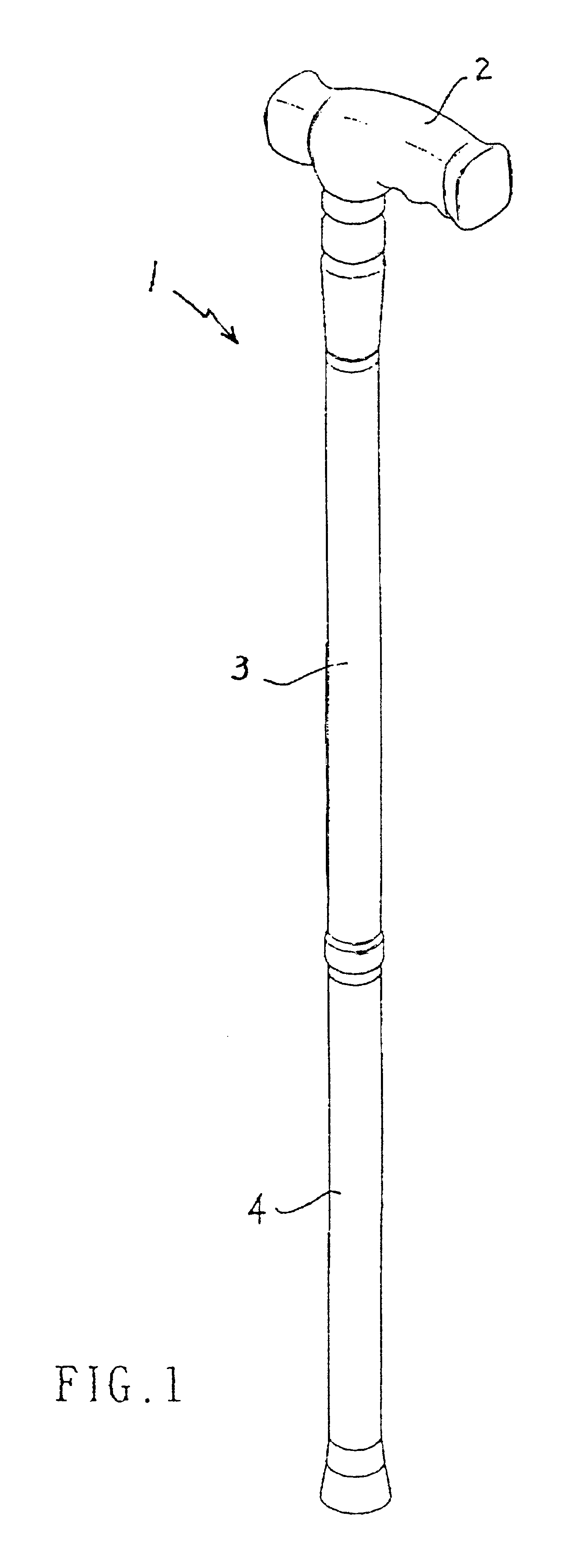
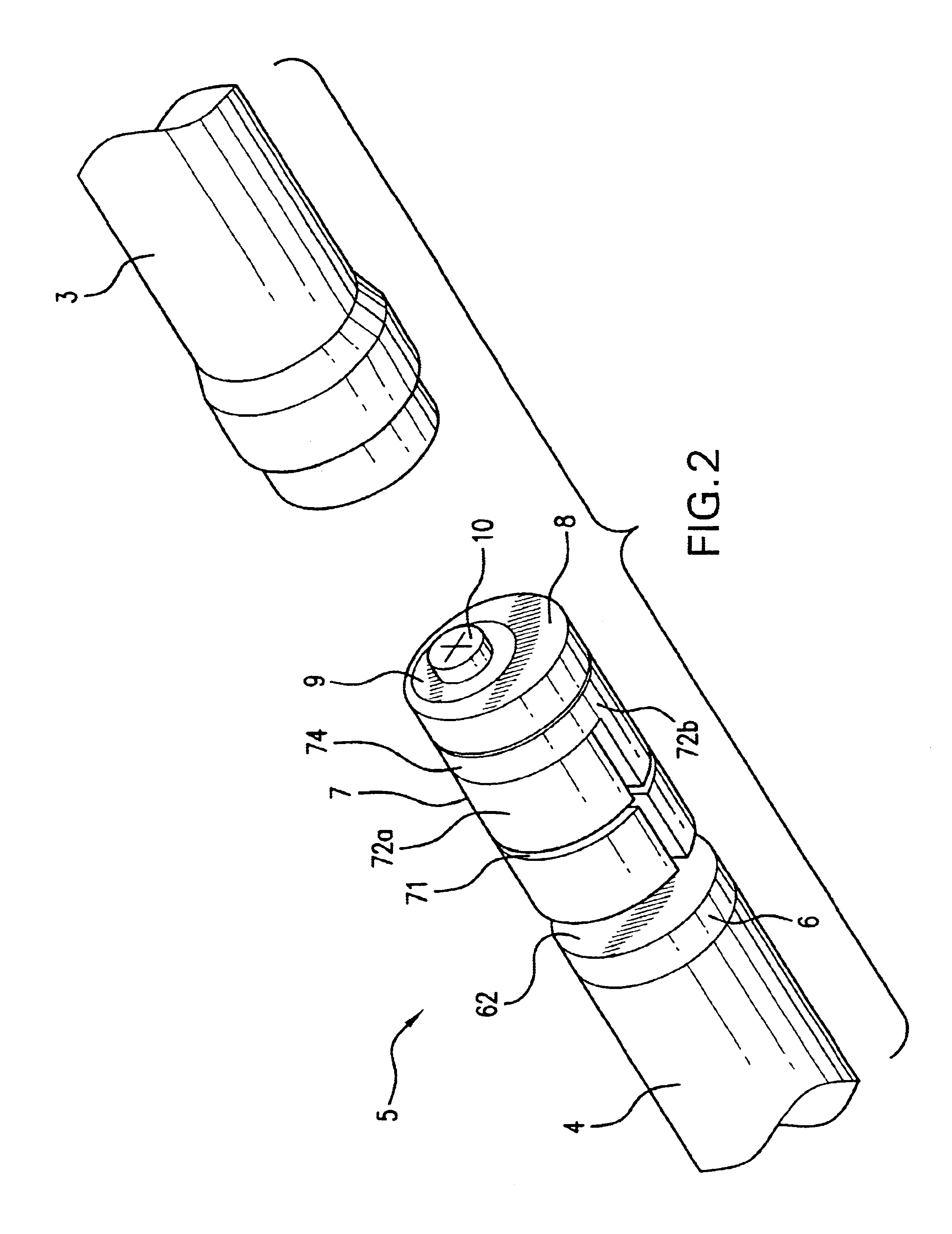
In the present invention as shown in FIGS. 2, 3, the walking stick 1 having a position retaining device 5 which enables a user to vary the length of the walking stick in a stageless manner. The position retaining device 5 is comprised of an retainer 7 including a round securing plate 74 in connection to a half cylindrical extension 72a, and another separated half cylindrical portion 72b in match with the cylindrical extension 72a.
Both the half cylindrical extension 72a and the half cylindrical portion 72b are provided with inner threads 77 and an outer groove 71 at the middle thereof and a tapered face 78 at one end respectively so as to form an expandable plastic tube having inner threads and a tapered bottom when the two separable portions 72a, 72b are bound together by a C-shaped clamp 73. On the top of the round securing plate 74 is disposed an eccentric engagement protrusion 76 having a screw hole 75 so as to permit a circular disk 8 having an eccentric hole 81 defined thereon ...
second embodiment
Referring to FIGS. 6, 7, the present invention is equipped with a position retaining device 5 having a circular disk 8 with an eccentric hole 81 and secured to an eccentrically operated retainer 12. The retainer 12 having an eccentric securing plate 122 for the fixing of the circular disk 8 by a screw 10. The retainer 12 has a conically tapered face 123 with an innerly threaded tubular extension 121 projected downwardly therefrom. On top of the securing plate 122 is erected a tubular protrusion 125 having a screw hole 124 for fixing the circular disk 8. A taper means 6 having a conically tapered face 62 and an outerly threaded post 63 extended therefrom is attached to the end of a lower pipe 4 by way of a joint block 61 and can adjustably engaged with the retainer 5. A plastic locking tube 11 having a longitudinally split opening 111 and a central hole 112 and a tapered periphery 113 at each end thereof is disposed between the eccentric retainer 12 and the taper means 6 whereby when...
third embodiment
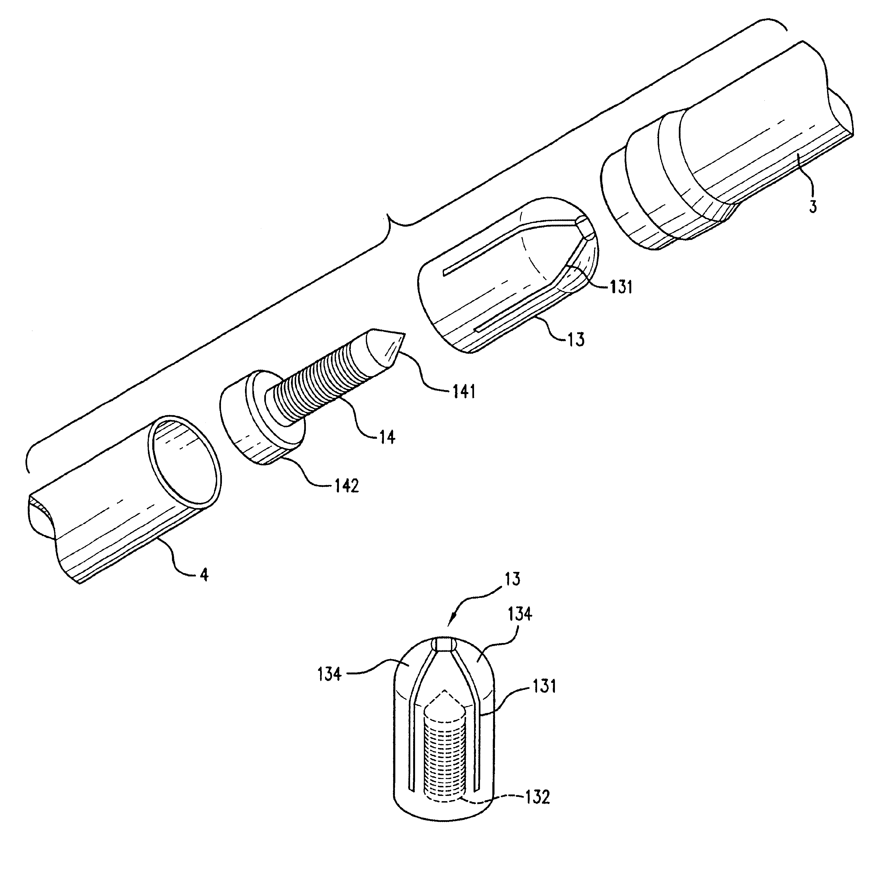
Referring to FIGS. 9, 10, 10a, 11, the present invention is equipped with a plastic retainer cap 13 having a tubular passage .[.133.]. .Iadd.132.Iaddend.. The plastic retainer cap 13 is divided into four symmetric portions 134 by two orthogonally defined splitting cuts 131. The tubular passage 132 is provided with inner threads 133 on the wall thereof so as to permit a threaded post 14 having a tapered end 141 and secured to the top end of the lower pipe 4 by the joint block 142 to be rotatably engaged with the plastic retainer cap 13. The innerly threaded tubular passage 132 extends most of the plastic retainer cap 13 with a section 135 thereof, adjacent the. four-portion split top end, left blank whereby when the tapered end 141 of the threaded post 14 is made to move forwardly as a result of the rotation of the lower pipe 4, the four split portions 134 of the plastic retainer cap 13 are urged to outwardly expand to firmly abut against the inner wall of the upper pipe 3 so as to l...
PUM
 Abstract
Description
Claims
Application Information
 - R&D
- Intellectual Property
- Life Sciences
- Materials
- Tech Scout
- Unparalleled Data Quality
- Higher Quality Content
- 60% Fewer Hallucinations
Browse by: Latest US Patents, China's latest patents, Technical Efficacy Thesaurus, Application Domain, Technology Topic, Popular Technical Reports.
© 2025 PatSnap. All rights reserved.Legal|Privacy policy|Modern Slavery Act Transparency Statement|Sitemap|About US| Contact US: help@patsnap.com


