


Quick Research
Generate reliable direction feasibility study reports for your R&D in just a few steps.

Technical Q&A
Discover and master advanced knowledge NOW. Basics, ideas, possibilities, all at once.

Find Solutions
As an expert in R&D theories, this can generate solutions to your technical problems instantly.

Evaluate Feasibility
Analyze your overall solution with one click, know your potential R&D risks in advance.

Monitor Landscape
Get weekly tech updates, stay abreast of the latest tech innovations and key insights.
Evaporative fuel-processing system for internal combustion engines
- Summary
- Abstract
- Description
- Claims
- Application Information
AI Technical Summary
Benefits of technology
Problems solved by technology
Method used
Image

Examples
first embodiment
FIG. 6 shows a program for carrying out the abnormality diagnosis of the evaporative emission control system 11, which is executed by the ECU 5 of the evaporative fuel-processing system according to the invention. This program is executed as background processing.
First, at a step S21, it is determined whether or not the flag FMON has been set to "1" in the monitoring condition-determining routine described above with reference to FIG. 5. Immediately after the engine 1 has been started, the monitoring conditions are not satisfied, and hence the answer to the question of the step S21 is negative (NO), so that the program proceeds to a step S22, where a first timer tmPTO, formed of a down-counter, is set to a predetermined time period T1, and started. The first timer tmPTO is provided to secure a sufficient time period for stabilizing the tank internal pressure PT after the tank internal pressure PT is relieved to the atmosphere, and accordingly the predetermined time period T1 assumes...
second embodiment
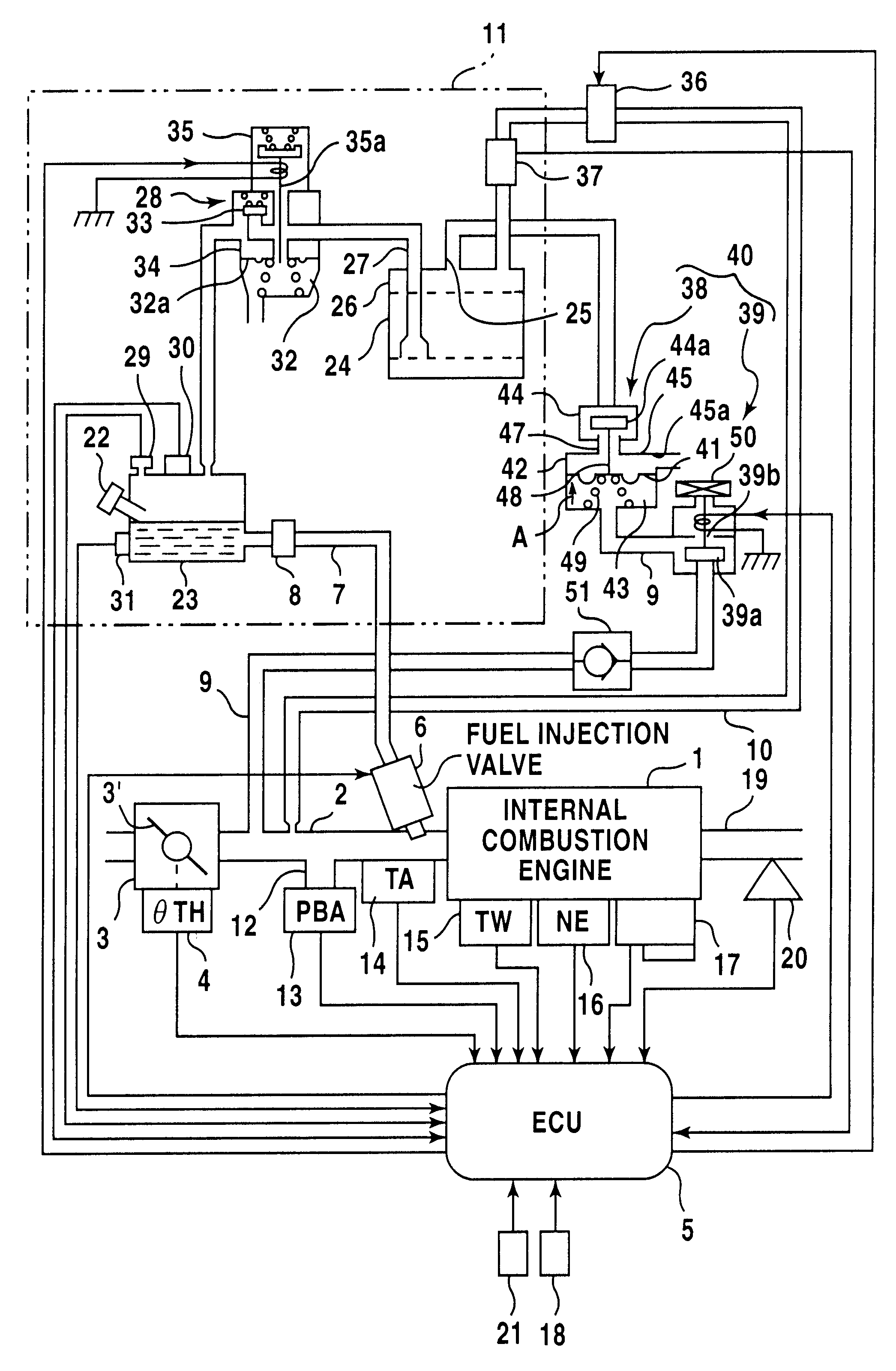
FIG. 13 shows changeovers of operative states of the first and second electromagnetic valves 35, 39, the drain shut valve 38, and the second control valve 36 of the system, and changes in the inside-tank pressure PT resulting therefrom, according to the invention. The operative states of the valves are changed over by respective corresponding signals supplied from the ECU 5 (CPU).
Under the normal operating condition (in the normal purging mode), during a time period indicated by (i) in FIG. 13, the first electromagnetic valve 35 is energized, while the second electromagnetic valve 39 is deenergized. When the ignition switch IGSW is closed and the IGSW sensor detects that the engine 1 is in operation, the purge control valve 36 is turned on or opened. Evaporative fuel generated in the fuel tank 23 then flows via the evaporative fuel-guiding passage 27 into the canister 26, where it is temporarily adsorbed by the adsorbent 24. Further, since the second electromagnetic valve 39 is in t...
PUM
 Abstract
Description
Claims
Application Information
 - R&D Engineer
- R&D Manager
- IP Professional
- Industry Leading Data Capabilities
- Powerful AI technology
- Patent DNA Extraction
Browse by: Latest US Patents, China's latest patents, Technical Efficacy Thesaurus, Application Domain, Technology Topic, Popular Technical Reports.
© 2024 PatSnap. All rights reserved.Legal|Privacy policy|Modern Slavery Act Transparency Statement|Sitemap|About US| Contact US: help@patsnap.com