
Electrically actuated friction brake

a friction brake and electric actuator technology, applied in the direction of actuators, brake actuating mechanisms, axially engaging brakes, etc., can solve the problems of high cost pressure, overdimension, and inability to optimally utilize electric actuators, so as to reduce the attainable actuation time and keep the friction brake inexpensive

Active Publication Date: 2018-05-15
ROBERT BOSCH GMBH
View PDF37 Cites 0 Cited by
  • Summary
  • Abstract
  • Description
  • Claims
  • Application Information

AI Technical Summary

Benefits of technology

This solution reduces actuation time and maintains cost-effectiveness by allowing the electrical actuator to operate efficiently across various braking conditions, achieving actuation times of around 180 ms with a pad pressing force of 40 kN, while also enabling a parking brake function.

Problems solved by technology

Available mounting space, weight, costs, and current requirement for the electrical actuator require that the motor power be kept low, which is why an optionally large electrical actuator cannot be used.
That is disadvantageous, however, because, in all other, generally more frequent cases, the electrical actuator cannot be optimally utilized and is over-dimensioned.
In addition, the cost pressure on electrically actuated brakes is also high, because they have to compete with relatively simple hydraulic brakes.
As a rule, the installation conditions of the brake, in particular for vehicle brakes, are such that only a very limited mounting space is available to receive the brake, so that electrical motors of small size have to be used.
But such transmissions are very complex and therefore also expensive.

Method used


Image

  • Electrically actuated friction brake
  • Electrically actuated friction brake
  • Electrically actuated friction brake

Examples


Embodiment Construction

[0013]Embodiments of the present invention seek to reduce the attainable actuation times of an electrically actuated friction brake and simultaneously to keep the friction brake inexpensive.

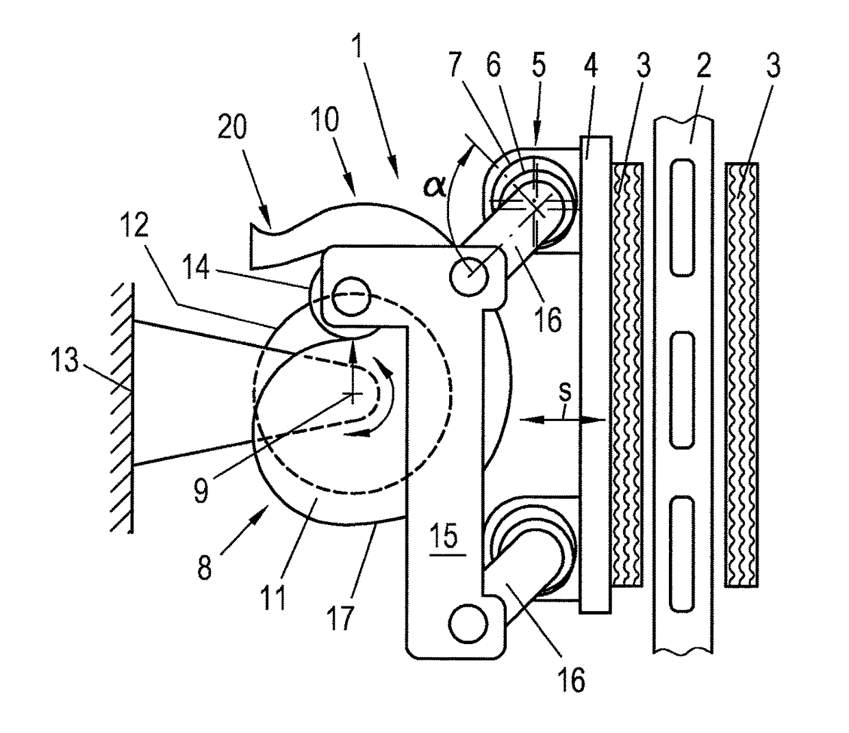
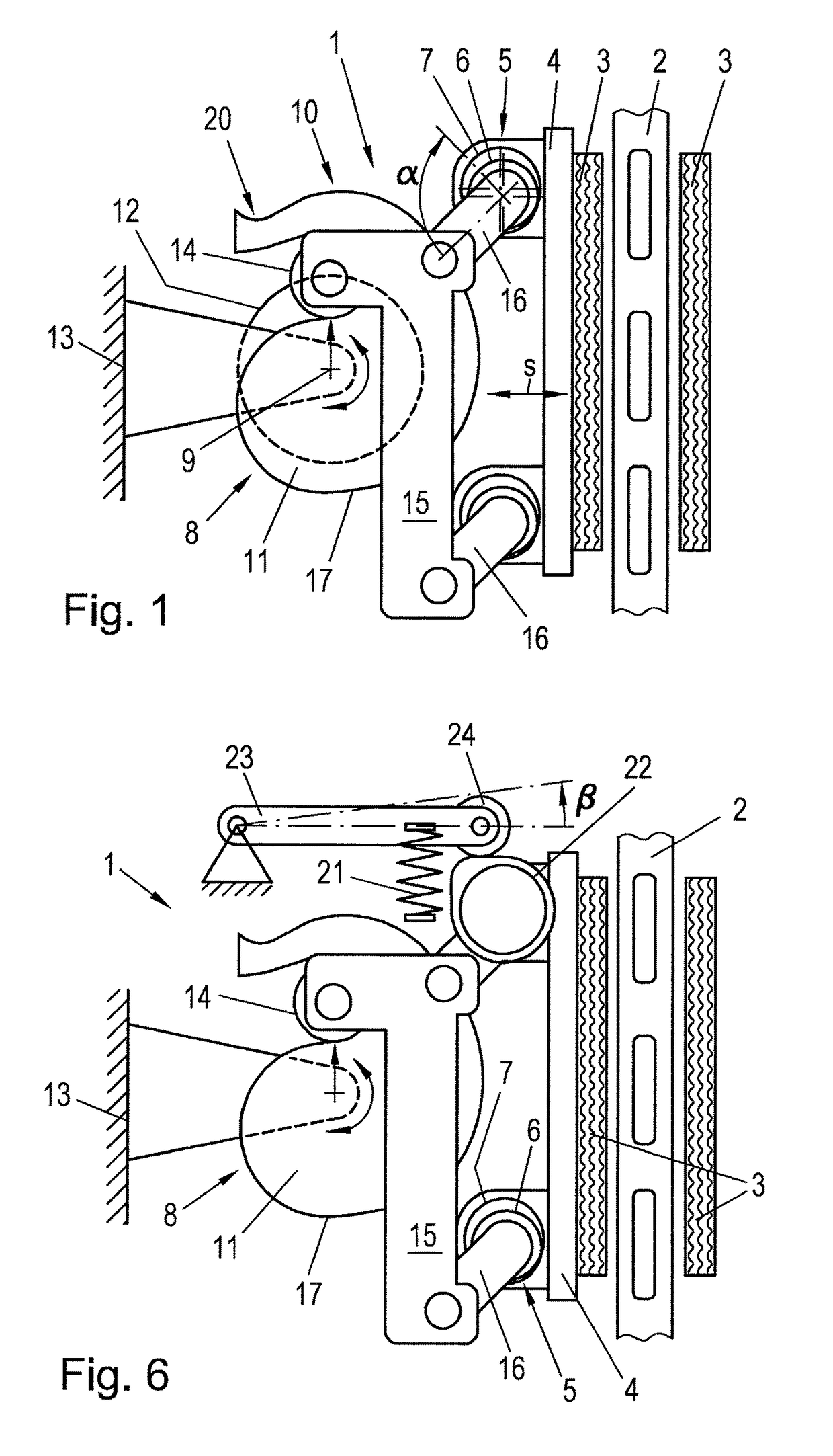
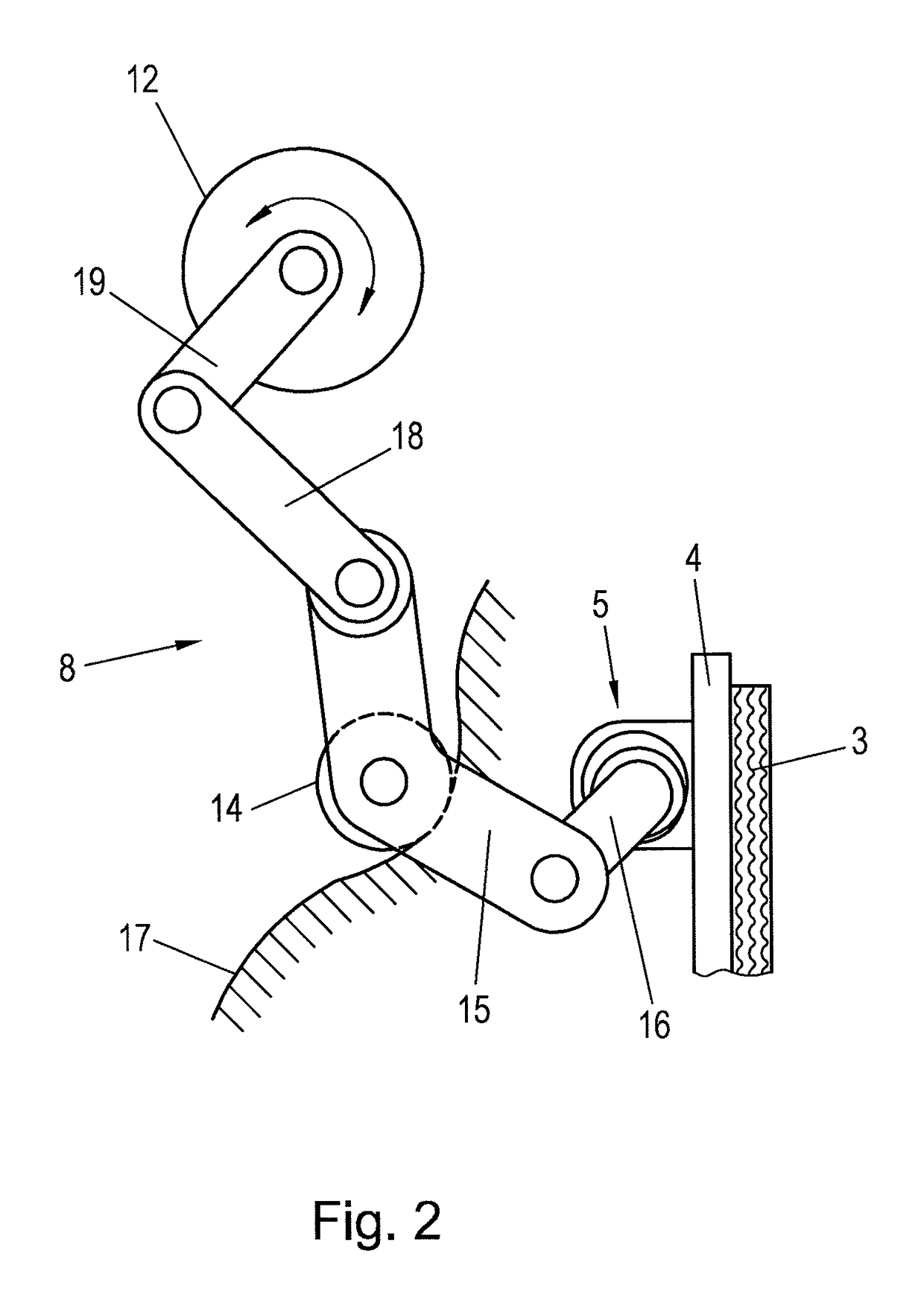
[0014]According to embodiments of the invention, for braking, the actuation device is driven by a spring and is held open by an electrical actuator, so that the spring actuates the friction brake in case of a power loss, wherein a first transmission element, that is connected to the brake pad, and a second transmission element with an elevation curve are provided and a coupling element is provided on the first transmission element, wherein a follower element is arranged on the coupling element that follows the elevation curve under the action of the spring for actuating the first transmission element. The second transmission element can supply much of the transmission required in the actuation device, whereby the electrical actuator is relieved. Due to the additional transmission of the second tr...


PUM


Abstract

To reduce the attainable actuation times of an electrically actuated friction brake and simultaneously keep the friction brake inexpensive, an electrically actuated friction brake with a brake pad (3) actuated by an actuation device (10) is proposed, wherein for braking the actuation device (10) is driven by a spring and is held open by an electrical actuator (12), so that the spring actuates the friction brake (1) in case of a power loss, wherein a first transmission element (5), that is connected to the brake pad (3), and a second transmission element (8) with an elevation curve (17) are provided and a coupling element (15) is provided on the first transmission element (5), wherein a follower element (14) is arranged on the coupling element (15) that follows the elevation curve (17) under the action of the spring for actuating the first transmission element (5).

Description

CROSS-REFERENCE TO RELATED APPLICATIONS[0001]The present application is a Continuation-in-Part of International Patent Application No. PCT / EP2014 / 054531 filed Mar. 10, 2014, which claims priority of Austrian Patent Application No. A50165 / 2013 filed Mar. 11, 2013. Moreover, the disclosure of International Patent Application No. PCT / EP2014 / 054531 is expressly incorporated by reference herein in its entirety.BACKGROUND OF THE INVENTION[0002]1. Field of the Invention[0003]Embodiments of the present invention relate to an electrically actuated friction brake with a brake pad actuated by an actuation device.[0004]Embodiments of the present invention relate to electrically actuated brakes, thus to brakes in which an electrical actuator such as an electric motor, via transmission parts such as levers, screws, ball screws, cams, eccentrics, fluids, gases, etc., presses on the brake pad, such as a brake disc for example, on the friction surface, such as a brake disc or brake drum, for example...

Claims


Application Information

Patent Timeline
Patent Type & Authority Patents(United States)
IPC IPC(8): F16D65/18F16D55/225F16D121/14F16D121/18F16D121/24F16D121/26F16D125/30F16D125/32F16D125/64F16D127/00
CPCF16D65/18F16D55/225F16D2121/14F16D2121/18F16D2121/24F16D2127/007F16D2125/30F16D2125/32F16D2125/64F16D2125/645F16D2121/26B60T13/74F16D65/14F16D65/16
Inventor PUTZ, MICHAEL
Owner ROBERT BOSCH GMBH
Learn More