Belt step conveyor system

a conveyor system and belt step technology, applied in the direction of thin material processing, printing, other printing apparatus, etc., can solve the problems of incorrect or less accurate positioning of loads on conveyor belts, difficult control of conveyor belts (b>1/b>), and difficulty in controlling them, so as to improve the resilience and tensioning of conveyor belts, reduce tensioning, and ensure the accuracy of positioning capabilities

Active Publication Date: 2018-05-15
AGFA NV
View PDF7 Cites 0 Cited by
  • Summary
  • Abstract
  • Description
  • Claims
  • Application Information

AI Technical Summary

Benefits of technology

[0017]The advantageous effect is that no slip occurs contrary to the belt step conveyor systems driven by a stepper motor to power a pulley (3). The exact positioning capabilities are also accurate and less tension force is needed on the conveyor belt to strengthen the resilience and tensioning of the conveyor belt.
[0018]Another advantage is the ease of implementation and use of the linear movement system in the embodiment of the belt step conveyor system to calculate the exact positioning of the load on the conveyor belt.
[0019]Another advantageous effect is that the engaging of the second belt gripper while the first belt gripper is returning to its end position ensures the stagnation of the conveyor belt and the load on the conveyor belt. This gives a more accurate positioning capability.
[0020]A preferred embodiment of the invention has a plurality of moving belt grippers to enlarge the force to carry the load on a conveyor belt from a start location to an end location. The force to carry the load on the conveyor belt from start location to end location can be divided by the linear movement systems of the plurality of moving belt grippers. The advantage is the need of linear movement systems with less linear force can be used, thereby obtaining a better control to drive the belt step conveyor system. A more preferred embodiment comprises a plurality of moving belt grippers mounted at each border, thus the left and the right border, of the conveyor belt. This allows to better control the straightness of the conveying path of the conveyor belt and a higher accuracy of position capabilities especially transverse to the conveying direction.
[0024]The use of an electro-magnet in a belt gripper is preferred because of the easy and fast control of the electro-magnet force. The belt gripper shall engage instantly the conveyor belt if the electro-magnet is powered on. The release of the conveyor belt is instantly done by powering off the electro-magnet. The instantly engaging and releasing from the belt gripper with an electro-magnet has the advantage of very high positioning capabilities. An electro magnet holder used as clamp for the conveyor belt is preferred.

Problems solved by technology

However, still the slip occurring on the powered pulley (3) and the conveyor belt (1) remains difficult to control.
This causes incorrect or less accurate positioning of a load on a conveyor belt.

Method used


Image

  • Belt step conveyor system
  • Belt step conveyor system
  • Belt step conveyor system

Examples


Embodiment Construction

Belt Step Conveyor System

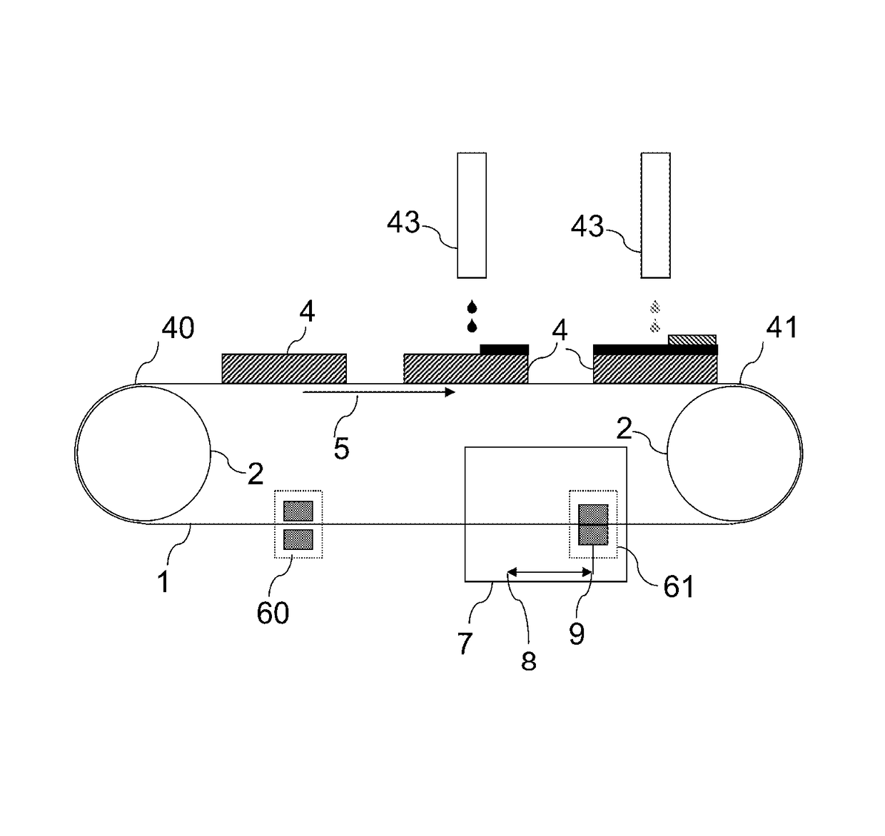
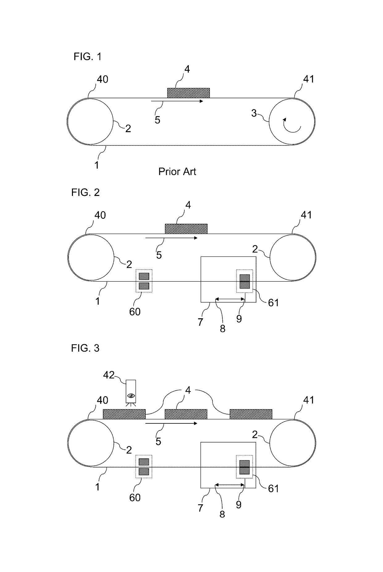
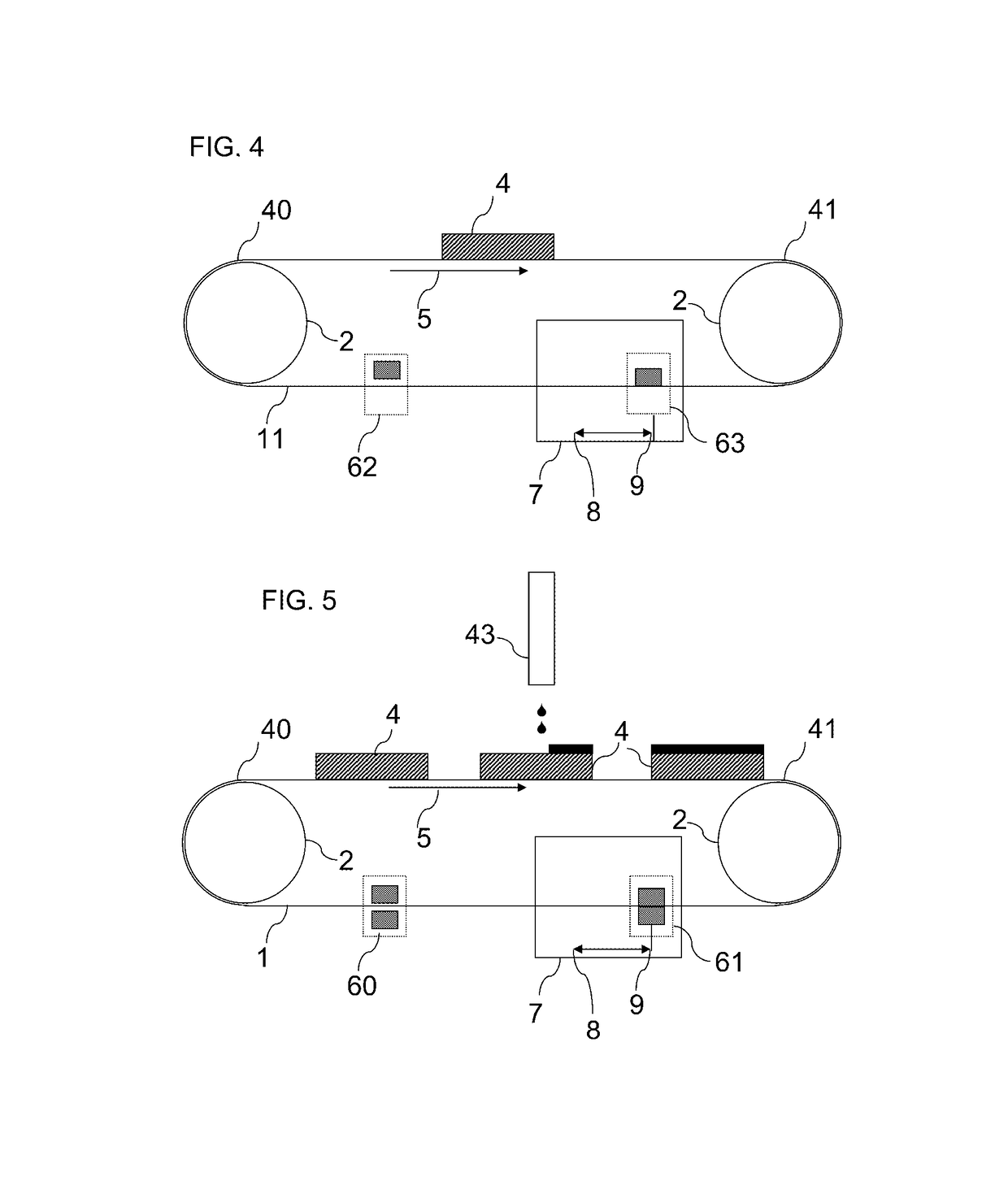
[0041]Preferred embodiments of the invention include a conveyor system and conveying method comprising a conveyor belt (1) linked with two pulleys or a plurality of pulleys to carry a load (4) with successive distance movements in a conveying direction (5) by a drive system that comprises:

[0042]a driving mean to drive and control a first linear movement system (7);

[0043]a first belt gripper that has a first engaging mean to engage the conveyor belt (1) when the first belt gripper is moved by the first linear movement system (7) from a home position (8) to an end position (9) and that has a first releasing mean to release the conveyor belt (1) when the first belt gripper is moved by the first linear movement system (7) from the end position to the home position;

[0044]a second belt gripper that has a second releasing mean to release the conveyor belt (1) when the first belt gripper is moved by the first linear movement system (7) from the home position (8) to ...


PUM


Abstract

A belt step conveyor system includes a moving belt gripper mounted on a linear movement system to convey the conveyor belt rotating about a plurality of pulleys in successive distance movements while the moving belt gripper engages the conveying belt and the moving belt gripper is moved from a home position to an end position by linear movement system. The conveyor belt is stagnant by engaging a stagnating belt gripper while the moving belt gripper moves back to its home position, else the stagnating belt gripper releases the conveyor belt.

Description

CROSS-REFERENCE TO RELATED APPLICATIONS[0001]This application is a 371 National Stage Application of PCT / EP2014 / 059819, filed May 14, 2014. This application claims the benefit of European Application No. 13167784.1, filed May 15, 2013, which is incorporated by reference herein in its entirety.BACKGROUND OF THE INVENTION[0002]1. Field of the Invention[0003]The invention relates to the transport of a load, for example an ink-receiver in an inkjet printer, with a conveyor belt system with high accurate successive distance movements to have the availability to manipulate or check the load on accurate positions between or during the successive distance movements.[0004]2. Description of the Related Art[0005]A state-of-the art step conveyor system as shown in FIG. 1, also called a step conveyor or stepper conveyor, is a piece of mechanical handling equipment that carries a load (4) by moving from a start location (40) to an end location (41) in successive distance movements also called dis...

Claims


Application Information

Patent Timeline
Patent Type & Authority Patents(United States)
IPC IPC(8): B41J2/165B41J11/00B65H5/22
CPCB41J11/007B65H5/224B65H2555/26B65H2513/40B65H2404/25
Inventor DE ROECK, LUCPIRON, ERICZWIJSEN, JAN
Owner AGFA NV
Why Eureka
Try Eureka