
Remote controlled switch cover

a remote control and switch cover technology, applied in the field of home automation and control arts, can solve the problems of expensive equipment, many homeowners are incapable or unwilling to perform such rewiring, and purchase expensive equipmen

Active Publication Date: 2018-05-01
ECOLINK INTELLIGENT TECH
View PDF11 Cites 92 Cited by
  • Summary
  • Abstract
  • Description
  • Claims
  • Application Information

AI Technical Summary

Benefits of technology

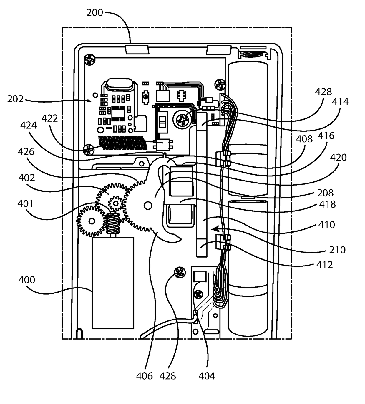
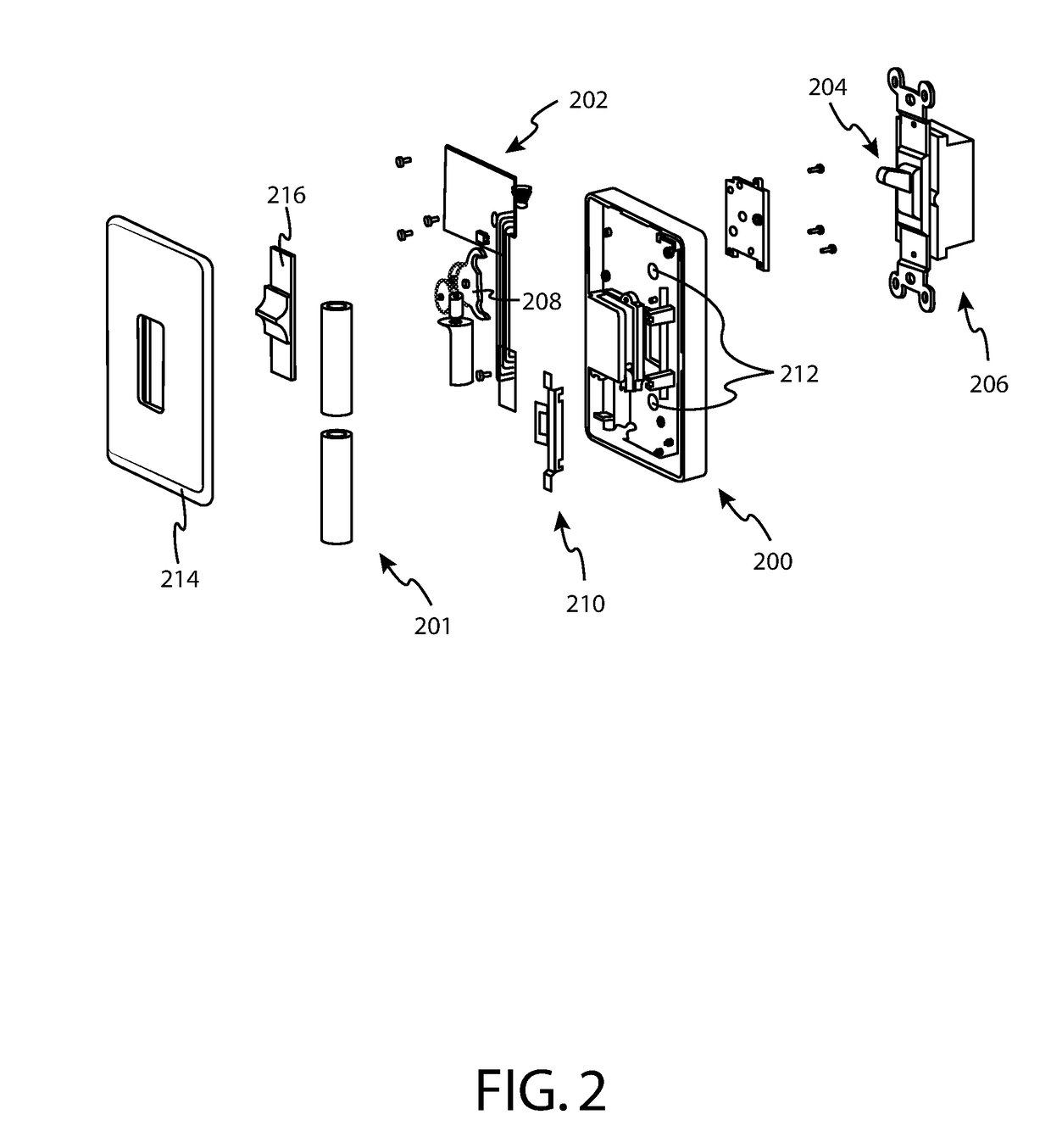
The patent describes a switch cover that can be installed on a standard toggle switch to turn it into a remote-controlled switch. The cover has a switch toggle member that can be moved to activate or deactivate the switch. The cover also has a gear train and an electric motor that work together to move the toggle member in both directions. The switch cover also has a receiver for receiving signals that activate the switch and processing circuitry that causes the motor to rotate and move the toggle member. The technical effect of this invention is that it allows for easy remote control of a standard toggle switch with a simple switch cover.

Problems solved by technology

However, it is generally necessary to purchase expensive equipment to enable such a feature, such as expensive Wi-Fi capable light bulbs, or Wi-Fi enabled light switches.
Such Wi-Fi enabled light switches typically require replacement of the entire light switch, which potentially requires access to household AC voltages.
Understandably, many homeowners are incapable or unwilling to perform such re-wiring.

Method used


Image

  • Remote controlled switch cover
  • Remote controlled switch cover
  • Remote controlled switch cover

Examples


Embodiment Construction

[0020]Embodiments of the present invention allow a conventional electrical switch to be converted into a remote-controlled switch simply and economically. In one embodiment, a conventional toggle switch is converted into a remote-controlled switch by simply replacing its switch cover with a switch cover in accordance with the teachings herein.

[0021]A remote controlled switch cover assembly may be used to convert a standard, existing toggle switch to one that can be controlled remotely, for example wirelessly using a keyfob or by using a smartphone, tablet, or other personal electronic device through via a local gateway device, or via the Internet and a local gateway device, in instances where the controller is located remotely from the toggle switch. In some embodiments, a remote controlled switch may be controlled via a local security panel or home automation gateway, either alone or in conjunction with the aforementioned wireless devices. In one embodiment, the remote controlled s...


PUM


Abstract

A light switch cover for converting a standard toggle switch into a remote-controlled toggle switch. In one embodiment, the light switch cover comprises a switch toggle member for acting upon a toggle light switch member to place the toggle light switch member into either an on position or an off position, a gear train coupled to the switch toggle member that causes the switch toggle member to act upon the toggle light switch member, an electric motor, coupled to the gear train, for driving the gear train in a first direction to cause the switch toggle member to place the toggle light switch member into the on position, and for driving the gear train in a second direction to cause the switch toggle member to place the toggle light switch member into the off position, motor driving circuitry coupled to the electric motor, a receiver for receiving signals that cause actuation of the standard toggle switch, and processing circuitry coupled to the receiver and the motor driving circuitry that causes the light switch cover to receive a signal to turn the toggle switch into the on position and, in response, causing the electric motor to rotate in a direction to cause the switch toggle member to place the toggle light switch member into the on position.

Description

CROSS-REFERENCE TO RELATED APPLICATIONS[0001]The present application is a continuation-in-part of U.S. patent application Ser. No. 14 / 825,117 filed on Aug. 12, 2015, which claims the benefit of U.S. Provisional Application No. 62 / 036,581, filed on Aug. 12, 2014, the entirety of both which are incorporated by reference herein.BACKGROUND[0002]I. Field of Use[0003]The present application relates generally to the home automation and control arts. More specifically, embodiments of the present invention relate to remote control of electrical devices.[0004]II. Description of the Related Art[0005]Home automation and control has been gaining popularity in recent years, allowing homeowners to remotely monitor and control various devices in their home. For example, the Nest thermostat has revolutionized the home thermostat market by intelligently learning the usage habits of home occupants, while also allowing remote control of the thermostat via the Internet. Wi-Fi enabled light bulbs are bec...

Claims


Application Information

Patent Timeline
Patent Type & Authority Patents(United States)
IPC IPC(8): H01H3/04H01H23/14H01H23/04
CPCH01H23/04H01H23/145H01H2300/03
Inventor BAILEY, MICHAELWANG, ERIC
Owner ECOLINK INTELLIGENT TECH
Learn More