
Characterising robot environments

a robot environment and characterisation technology, applied in the field of spatial characterisation, can solve the problems of limiting the range of surgical procedures that can be carried out by such systems, affecting the operation efficiency of the operation, and the possible spatial relationship between the arms, so as to achieve the effect of modifying the arm configuration

Active Publication Date: 2018-04-17
CMR SURGICAL LTD
View PDF41 Cites 47 Cited by
  • Summary
  • Abstract
  • Description
  • Claims
  • Application Information

AI Technical Summary

Problems solved by technology

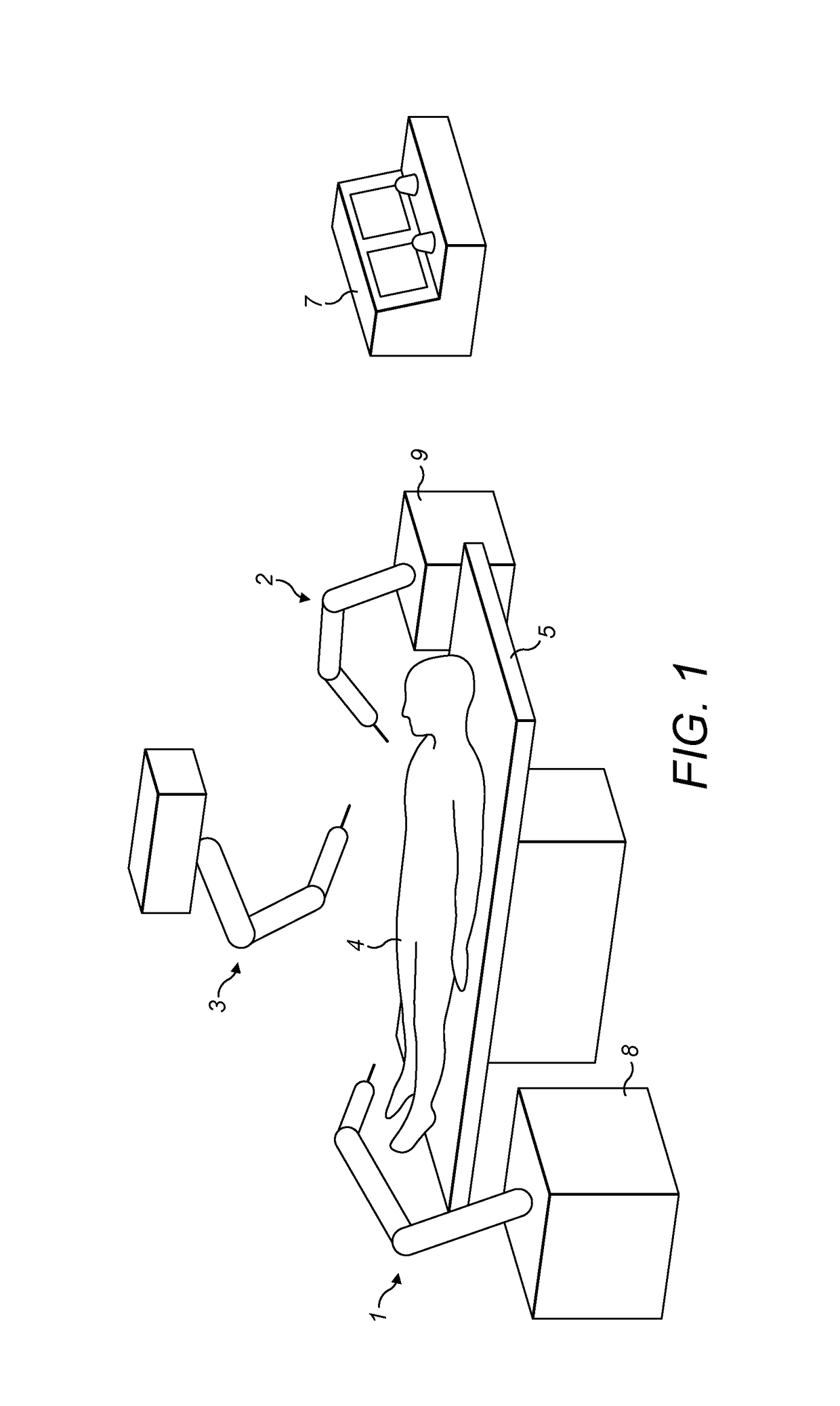
However, these systems are bulky, making them difficult to move into place in an operating theatre.
Also, the range of possible spatial relationships between the arms is limited by the fact that the arms stem from a single base, and this restricts the range of surgical procedures that can be carried out by such systems.
This is time-consuming because to fully characterise the spatial relationships in three dimensions many such measurements would be needed, and there is the possibility that errors might be made in taking the measurements or entering them in.

Method used


Image

  • Characterising robot environments
  • Characterising robot environments
  • Characterising robot environments

Examples


Embodiment Construction

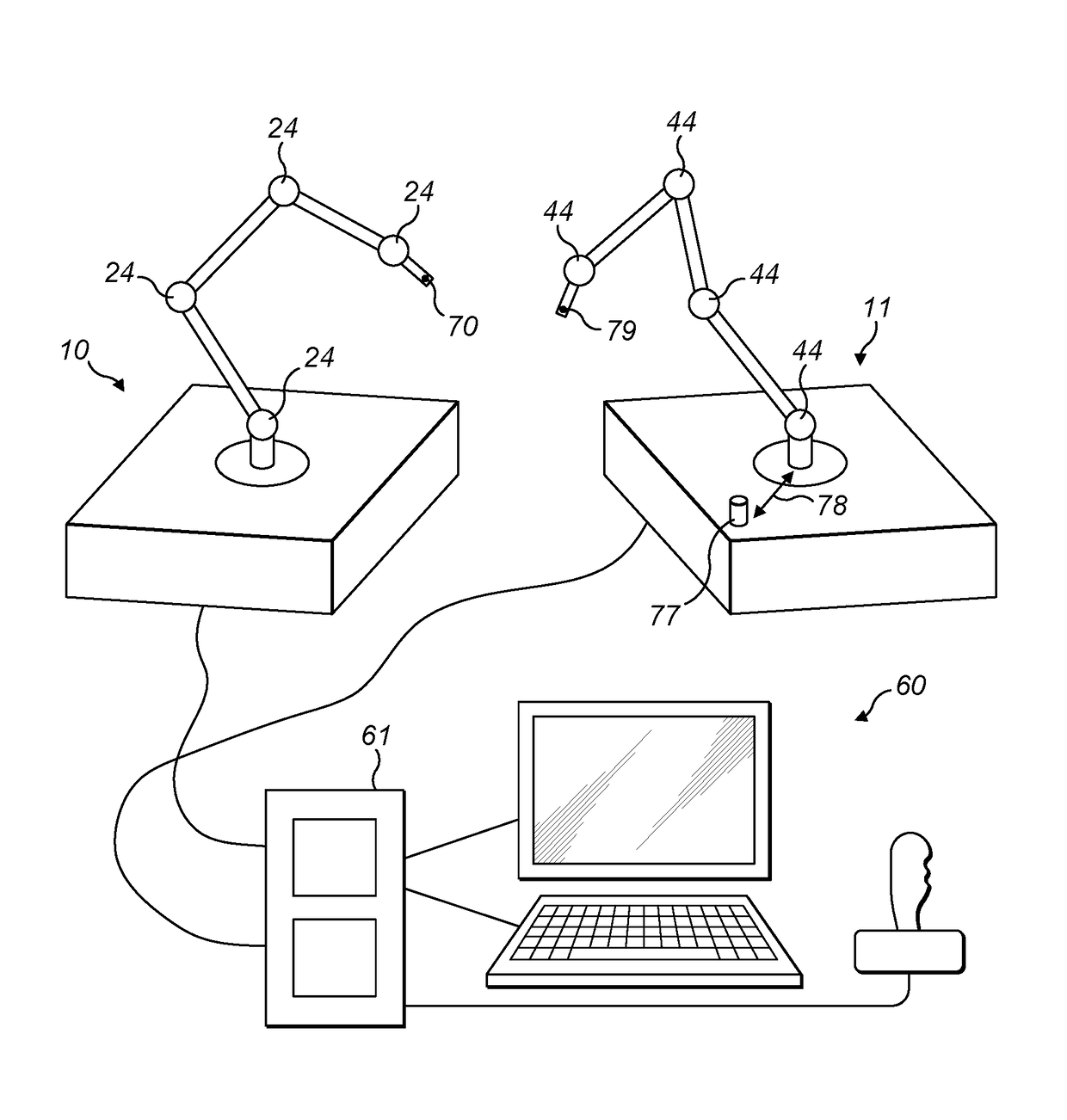
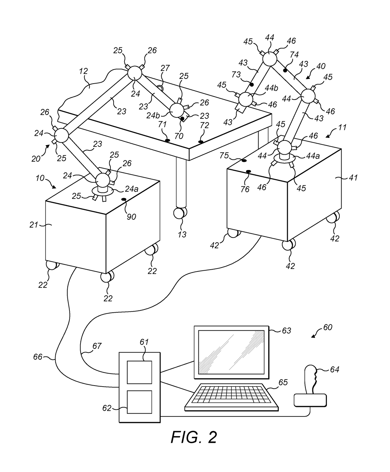
[0034]A surgical robot may have an arm that is flexible by virtue of a series of joints arranged along the arm which allow the arm to be reconfigured. The robot may be able to sense the configuration of its joints. When it is necessary to calibrate the robot's knowledge of its position relative to other furniture in the operating environment, for example another robot or an operating table, a first datum point on the arm can be moved into contact with a second datum point on the other furniture. By sensing the configuration of the arm when it is in contact with the second datum point the spatial relationship between the arm and the other furniture can be estimated. That relationship can then be used as data for controlling the robot during a subsequent procedure, for example to inhibit collision between the robot arm and the furniture.

[0035]FIG. 2 shows an example of a surgical environment. Robots shown generally at 10 and 11 are placed near a table 12 in preparation for performing ...


PUM


Abstract

A method for characterizing the environment of a robot, the robot having a flexible arm having a plurality of joints, a datum carried by the arm, a plurality of drivers arranged to drive the joints to move and a plurality of position sensors for sensing the position of each of the joints, the method comprising: contacting the datum carried by the arm with a first datum on a second robot in the environment of the first robot, wherein the second robot has a flexible arm having a plurality of joints, and a plurality of drivers arranged to drive those joints to move; calculating in dependence on the outputs of the position sensors a distance between a reference location defined in a frame of reference local to the robot and the first datum; and controlling the drivers to reconfigure the first arm in dependence on at least the calculated distance.

Description

CROSS-REFERENCE TO RELATED APPLICATION[0001]This application claims the benefit under 35 U.S.C. § 119 of United Kingdom Patent Application No. 1509341.2 filed on May 29, 2015 which is hereby incorporated herein by reference in its entirety for all purposes.BACKGROUND OF THE INVENTION[0002]This invention relates to characterising the spatial relationships of objects around robots, for example surgical robots.[0003]Some surgical robots are of considerable bulk and comprise multiple surgical arms stemming from a single fixed or mobile base. In these systems the fact that the surgical arms are mechanically attached to a common base means that the spatial relationship between the arms is inherent and can readily be established through knowledge of the arms' configurations. However, these systems are bulky, making them difficult to move into place in an operating theatre. Also, the range of possible spatial relationships between the arms is limited by the fact that the arms stem from a si...

Claims


Application Information

Patent Timeline
Patent Type & Authority Patents(United States)
IPC IPC(8): B25J9/00A61B34/30A61B34/32B25J9/16
CPCB25J9/1692A61B34/30A61B34/32B25J9/1679B25J9/1682G05B2219/39135G05B2219/39021G05B2219/39399G05B2219/39024G05B2219/39026G05B2219/39047G05B2219/39051Y10S901/09Y10S901/15Y10S901/46B25J9/1656B25J9/1666
Inventor HARES, LUKE DAVID RONALD
Owner CMR SURGICAL LTD
Learn More