
Methods and systems for automatic control of subjective image quality in imaging of objects

a technology of subjective image quality and automatic control, applied in the field of imaging systems, can solve the problems of time-consuming and operator-dependent, inexperienced users may generate sub-optimal images, and increase the risk of incorrect diagnosis

Active Publication Date: 2018-03-20
CONTEXTVISION
View PDF11 Cites 16 Cited by
  • Summary
  • Abstract
  • Description
  • Claims
  • Application Information

AI Technical Summary

Benefits of technology

The present invention provides improved methods and systems for automatic control and optimization of scan or system parameters of ultrasound imaging systems. The invention involves a control system that uses a trained network to identify and correct image features that correlate to subjective expert image preferences. The system can adjust system parameters to achieve desired image quality and can be used for creating new images. The invention can also be applied to other imaging systems such as magnetic resonance imaging (MRI), computed tomography (CT), X-ray imaging, positron emission tomography (PET), mammography, and ultrasound.

Problems solved by technology

In general, for a typical ultrasound scanner, a user needs to perform multiple operations to obtain optimized images, which is time consuming and operator dependent.
Furthermore, an inexperienced user may generate sub-optimal images due to sub-optimal settings that may increase the risk of an incorrect diagnosis.
However, this approach does not take into account any patient specific variations, which in fact is very important in ultrasound imaging to obtain an optimal image quality.

Method used


Image

  • Methods and systems for automatic control of subjective image quality in imaging of objects
  • Methods and systems for automatic control of subjective image quality in imaging of objects
  • Methods and systems for automatic control of subjective image quality in imaging of objects

Examples


Embodiment Construction

[0048]In the drawings, similar or corresponding elements are denoted by the same reference numbers.

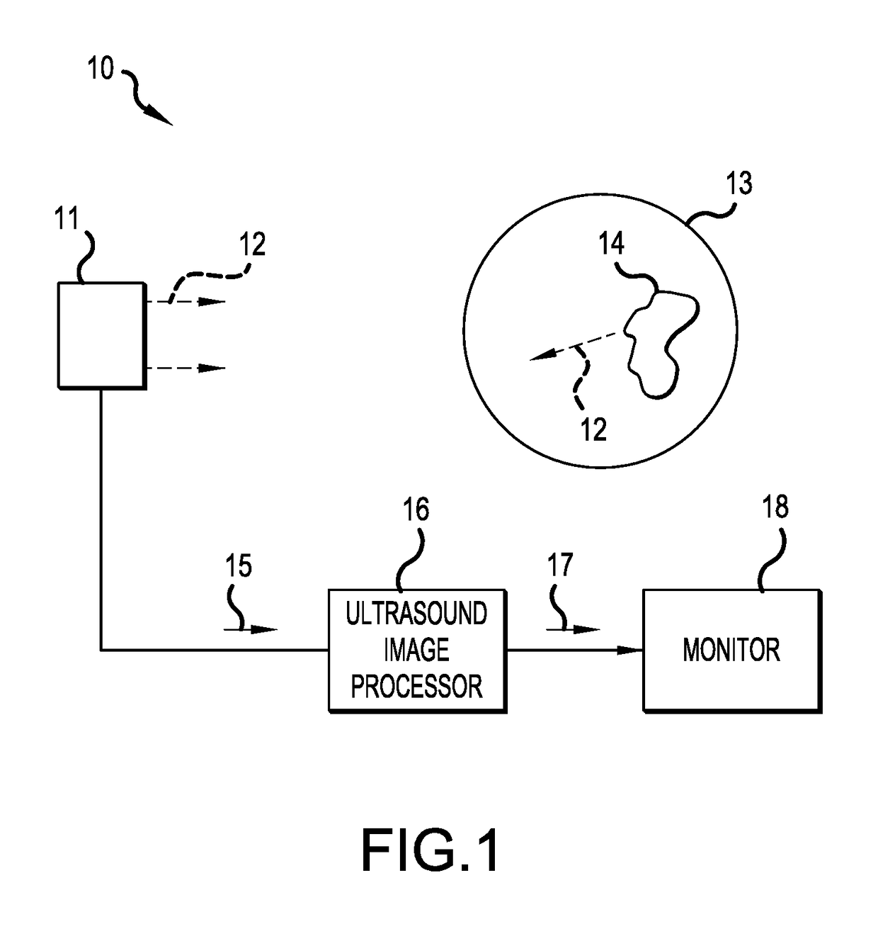
[0049]With reference first to FIG. 1, a general ultrasound imaging system in which the present invention can be implemented will be discussed. An ultrasound system 10 comprises a probe 11, including for example, an ultrasound transducer array having a set of transducer elements, for generating ultrasound acoustic signals 12 that are typically directed in a scan plane 13, e.g. behind a skin surface or in a body cavity such as in the human body. Although a 20 scan plane 13 is described, the scan plane 13 may also comprise a 30 scan region.

[0050]The acoustic signals 12 are reflected by objects or structures 14 in the scan plane 13 and return to the probe 11 or the transducer elements). The transducer elements in the probe 11 convert the reflected ultrasound acoustic signals 12 into a set of corresponding electrical signals 15, and transmit those signals 15 to an ultrasound image processor...


PUM


Abstract

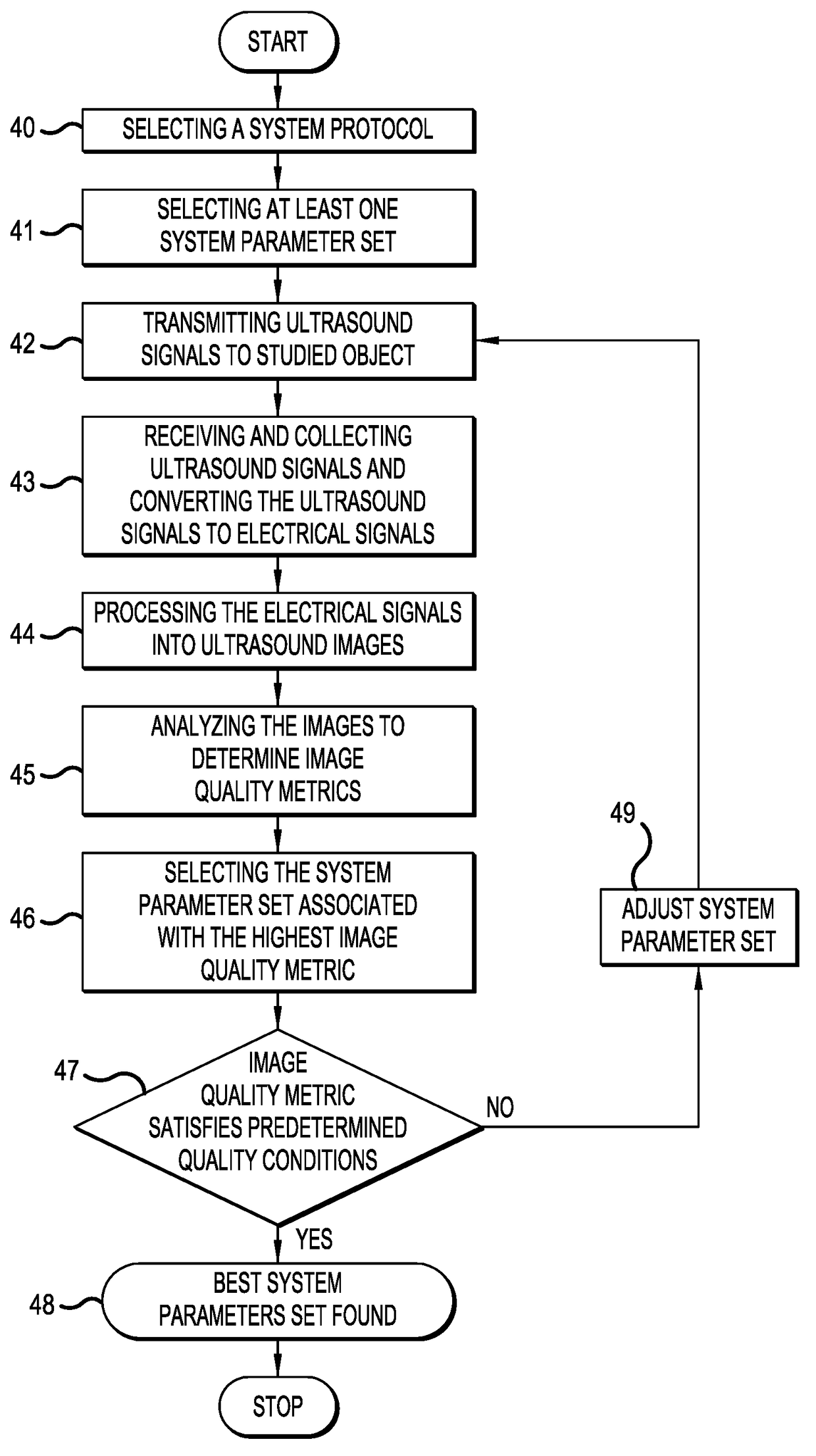
The present invention relates to method and system for automatic control of image quality in imaging of an object using, for example, an ultrasound system. The method comprises transmitting image generating signals into the object using selected system parameter sets of the imaging system. The imaging system has a number of different system parameter sets based on an image ranking measure reflecting a subjective expert opinion of a pre-defined set of images. The captured images are analyzed with respect to at least one image quality feature to determine an image quality metric for each image. The respective image quality metric for each image are analyzed to identify an image associated with a highest image quality metric and the system parameter set used for generating the image associated with the highest image quality metric can be selected as system parameter set for imaging of the object.

Description

CROSS-REFERENCE RELATED APPLICATION[0001]This application is a Continuation-In-Part of pending U.S. patent application Ser. No. 14 / 476,406, filed on Sep. 3, 2014. The entire contents of which are hereby incorporated by reference.TECHNICAL FIELD[0002]The present invention relates generally to imaging systems and method for such systems. More particularly, the present invention relates to methods and systems for automatic image optimization in imaging systems. Certain aspects of the present invention relates to methods and systems for automatic image optimization in ultrasound imaging systems.BACKGROUND OF THE INVENTION[0003]The use of ultrasound to produce images for medical monitoring and diagnosis has become wide spread to a large extent as a result from its nonionizing nature and its ability to produce images resulting from the inherent differences in properties of various soft tissues. Typical and common applications include examination and monitoring of the heart, abdomen and fe...

Claims


Application Information

Patent Timeline
Patent Type & Authority Patents(United States)
IPC IPC(8): A61B8/00A61B5/055A61B5/00A61B6/03G06N3/04A61B6/00A61B8/14G06N3/08G06T7/00
CPCA61B8/54A61B5/055A61B5/4312A61B6/032A61B6/037A61B6/487A61B6/545A61B8/14G06N3/0445G06N3/08G06T7/0012A61B5/0035G06T2207/20084G06T2207/10132G06T2207/20081A61B8/5223A61B8/585G01S7/52046G01S7/5205G16H50/30G06N3/044
Inventor HEDLUND, MARTINFARNEBACK, GUNMARKEMPE, MARTINKIMIAEI, SHAROKKOVAMEES, PETER
Owner CONTEXTVISION
Learn More