
Back-of-cab fuel system and vehicle assemblies

a fuel system and back-of-cab technology, applied in the direction of vehicle body streamlining, loading-carrying vehicle superstructure, propulsion parts, etc., can solve the problems of unused space between the cab and the back wall of the cab, and the wide width of the back-of-cab fuel system to provide optimal fuel capacity, etc., to achieve tight turning radius, shorten the wheel base of the tractor unit, and more compact arrangement

Active Publication Date: 2018-03-13
AGILITY FUEL SYST LLC
View PDF14 Cites 3 Cited by
  • Summary
  • Abstract
  • Description
  • Claims
  • Application Information

AI Technical Summary

Benefits of technology

[0004]In the past, back-of-cab fuel systems providing optimal fuel capacities were often too wide to fit well within the space adjacent to the cab backwall, e.g., to be disposed within the area of the fairings. As a result, a certain amount of empty space was left unused between the cab and the fuel system. As part of the inventions herein there was the realization that the fuel system should be configured in a way to make the best use of the space on the frame rail, by enabling a back-of-cab fuel system to be positioned closer to the cab. It was realized that if the unused space between the cab and the front of the fuel system could be reduced or eliminated, a more compact arrangement would result. These more compact arrangements would have a number of advantages, such as enabling other components to be mounted on a frame rail without lengthening the rail or wheelbase. These more compact arrangements also would allow shortening the wheel base of the tractor unit. A shorter wheel base vehicle would be lighter and would have a tighter turning radius, among other benefits.

Problems solved by technology

In the past, back-of-cab fuel systems providing optimal fuel capacities were often too wide to fit well within the space adjacent to the cab backwall, e.g., to be disposed within the area of the fairings.
As a result, a certain amount of empty space was left unused between the cab and the fuel system.

Method used


Image

  • Back-of-cab fuel system and vehicle assemblies
  • Back-of-cab fuel system and vehicle assemblies
  • Back-of-cab fuel system and vehicle assemblies

Examples


Embodiment Construction

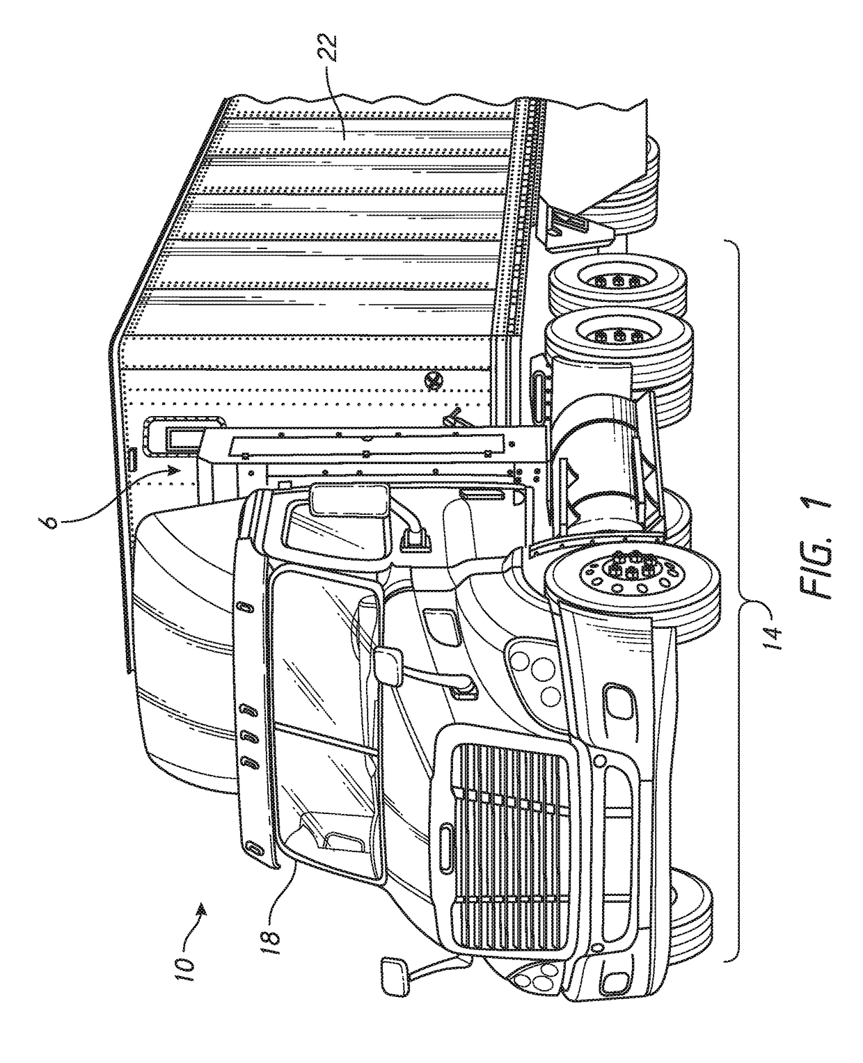
[0024]This application is directed to techniques to enhance the arrangement of a fuel system 6 and in some embodiments other components of a heavy duty truck, e.g., onto a tractor unit 14 of a truck 10. FIG. 1 shows that the fuel system 6 disposed between a cab 18 and a semi-trailer unit 22. Improvements are discussed that enable the fuel system 6 to be placed closer to a back wall of the cab 18 when integrated onto a vehicle with an aerodynamics package than had previously been known. As a result, wasted space between the cab 18 and the fuel system 6 can be reduced. This improved arrangement provides a number of advantages, including reducing weight and / or increasing configurability of a frame rail and / or reducing turning radius of the tractor unit 14 and a truck with which it is coupled and further advantages discussed herein.

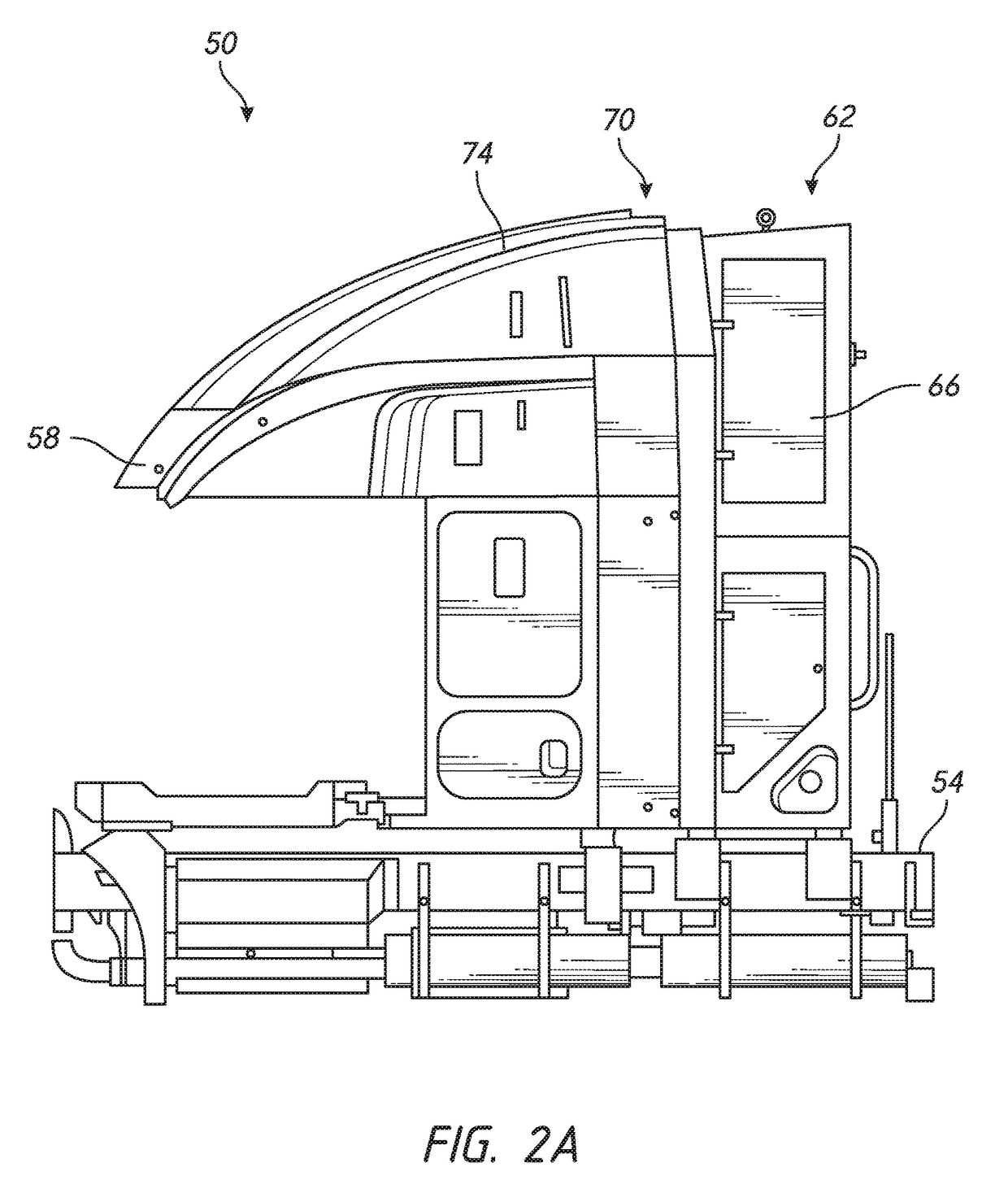
[0025]FIGS. 2A and 2B show an example embodiment of a vehicle assembly 50 that includes a frame rail 54 and a cab 58 supported thereby. A fuel system 62 is d...


PUM


Abstract

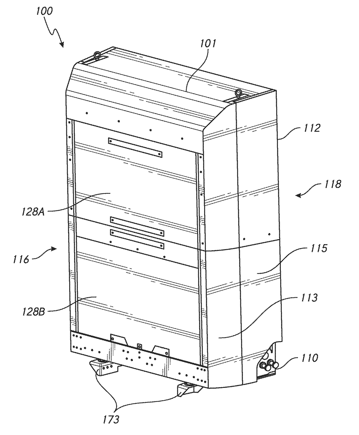
A fuel system for a vehicle is provided. The fuel system is configured to couple to a frame rail of the vehicle. A fuel system frame assembly of the fuel system is configured to couple with the frame rail directly or with another component that is coupled, directly or indirectly, with the frame rail. A cowling of the fuel system can include a fuel pressure vessel. The fuel pressure vessel configured to be placed within and supported by the fuel system frame assembly. The fuel system is configured to enhance component arrangement efficiency when mounted to a vehicle frame rail.

Description

INCORPORATION BY REFERENCE TO ANY PRIORITY APPLICATIONS[0001]This application claims priority to U.S. Provisional Application No. 62 / 329,934, filed on Apr. 29, 2016. The entire contents of the application identified above are incorporated by reference herein and made part of this specification.BACKGROUND OF THE INVENTIONField of the Invention[0002]This application is directed to a fuel system that can be positioned behind the cab of a heavy duty utility vehicle such as a truck or transit vehicle.Description of the Related Art[0003]Fuel systems are sometimes placed behind a cab of a heavy duty utility vehicle, such as a transit vehicle or a truck. This is a common practice in configuring a vehicle to run on compressed natural gas (CNG). CNG fuel systems have traditionally been spaced an inefficient amount from a rear portion of the cab of the vehicle. There are several reasons for this practice. A CNG powered vehicle is expected to provide a minimum diesel gallon equivalent (DGE) fue...

Claims


Application Information

Patent Timeline
Patent Type & Authority Patents(United States)
IPC IPC(8): B60K15/063B62D35/00B62D33/06
CPCB60K15/063B62D33/06B62D35/008B62D35/001B60K2015/0638B60K15/07
Inventor SLOAN, TODD F.FORSBERG, CHRIS
Owner AGILITY FUEL SYST LLC
Learn More