
Rotatable snowplow blade apparatus, systems and methods of using the same

a technology of snow shovel and blade, which is applied in the field of snow shovel, can solve the problems of not being able to push snow forward, having great difficulty in removing snow from near buildings or other structures, and snow shovels often have difficulties

Active Publication Date: 2018-02-06
STONE KEVIN
View PDF15 Cites 11 Cited by
  • Summary
  • Abstract
  • Description
  • Claims
  • Application Information

AI Technical Summary

Benefits of technology

This patent describes a snow pusher or box plow that can be used in areas where snow cannot be moved forward. It can move snow away from buildings or other structures and can also move snow both forward and rearward. The snow pusher has a blade that can be rotated between two positions to push and pull snow in different ways. This allows for more flexibility and efficiency in snow removal.

Problems solved by technology

While snow pushers may be utilized to move a large amount of snow completely out of the way (as opposed to merely deflecting snow to the side as in a snow plow), snow pushers often have difficulty in situations where there is limited space, and no ability to push snow forwardly.
For example, a snow pusher has great difficulty removing snow from near buildings or other structures because a snow pusher can only move the snow forward.

Method used


Image

  • Rotatable snowplow blade apparatus, systems and methods of using the same
  • Rotatable snowplow blade apparatus, systems and methods of using the same
  • Rotatable snowplow blade apparatus, systems and methods of using the same

Examples


Embodiment Construction

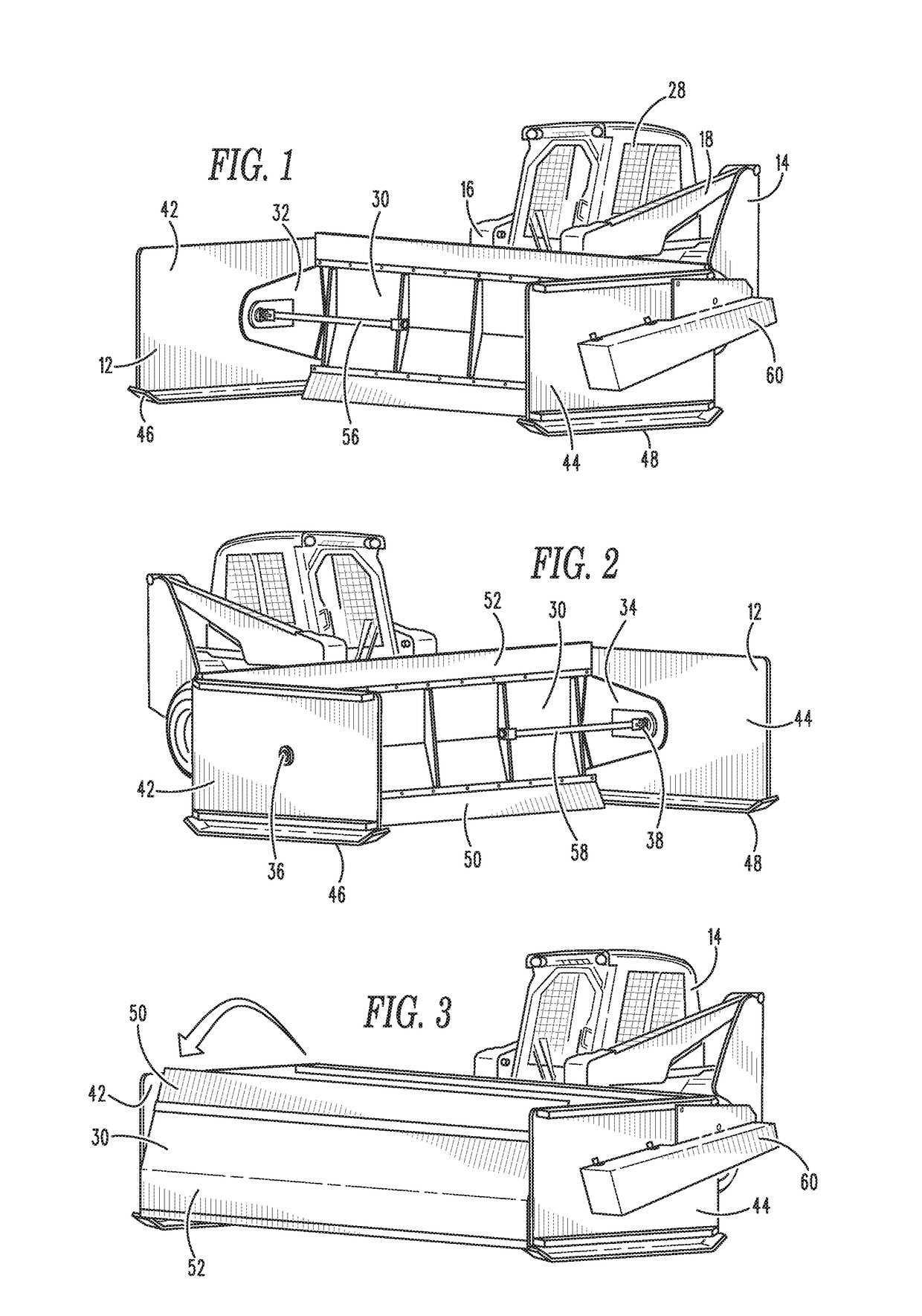
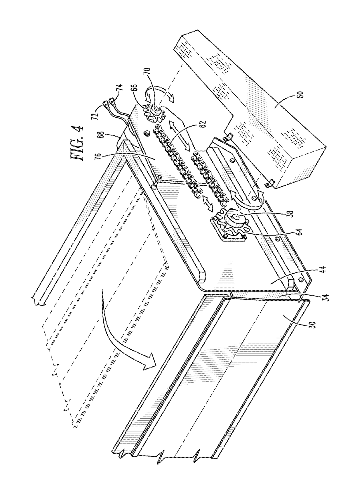
[0043]The present invention relates to a snow pusher, also known as a box plow. More specifically, the present invention relates to a snow pusher blade that may be disposed in a first position for pushing snow forwardly, as is typical of snow pushers, and may further be disposed in a second position for pulling snow rearwardly. The blade of the snow pusher may be contained within a snow plow box that may be reversible, allowing the blade to be disposed at a rear of the box for pushing the snow forwardly and at a front of the box for pulling snow rearwardly.

[0044]Now referring to the figures, wherein like numerals refer to like parts, FIGS. 1 and 2 illustrate a box plow system 10 in an embodiment of the present invention. The box plow system 10 comprises a box plow 12 removably attached to a skid loader 14, although it should be noted that the box plow 12 may be attached, either permanently or removably to any other mover and controller of the box plow 12, such as any tractor, front-...


PUM


Abstract

A snow pusher, also known as a box plow has a blade that is configured to be disposed in a first position for pushing snow forwardly, as is typical of snow pushers, and is further configured to be disposed in a second position for pulling snow rearwardly. The blade of the snow pusher may be contained within a snow plow box that may be reversible, allowing the blade to be disposed at a rear of the box for pushing the snow forwardly and at a front of the box for pulling snow rearwardly.

Description

TECHNICAL FIELD[0001]The present invention relates to a snow pusher, also known as a box plow. More specifically, the present invention relates to a snow pusher blade that may be disposed in a first position for pushing snow forwardly, as is typical of snow pushers, and may further be disposed in a second position for pulling snow rearwardly. The blade of the snow pusher may be contained within a snow plow box that may be reversible, allowing the blade to be disposed at a rear of the box for pushing the snow forwardly and at a front of the box for pulling snow rearwardly.BACKGROUND[0002]Plows for moving snow have been around for almost two hundred years, and the first patent for a snow plow to move snow from a railway is said to have been issued in the 1840s. Indeed, the first snow plows include wedges or blades affixed to horse drawn carriages that could move snow from roadways. The first plow affixed to motor equipment was recorded in 1913 by Good Roads Machinery company in Kennet...

Claims


Application Information

Patent Timeline
Patent Type & Authority Patents(United States)
IPC IPC(8): E01H5/06
CPCE01H5/061E01H5/065
Inventor STONE, KEVIN
Owner STONE KEVIN
Learn More