
Workpiece-shaping tool assembly

a technology for assembling tools and workpieces, applied in the direction of forming tools, metal-working feeding devices, positioning devices, etc., can solve the problems of high wear level and corresponding wear susceptibility problems, and achieve the effect of reducing wear, reducing wear, and reducing wear to the assembly

Active Publication Date: 2018-01-16
SMS MEER
View PDF15 Cites 0 Cited by
  • Summary
  • Abstract
  • Description
  • Claims
  • Application Information

AI Technical Summary

Benefits of technology

The present invention aims to provide an improved workpiece-shaping assembly that can overcome the disadvantages of the conventional assembly. Specifically, it aims to reduce the wear of the coupling between the drive shaft and the roll to increase the service life of the assembly and reduce costs accordingly.

Problems solved by technology

A disadvantageous aspect here is however the fact that use of this coupling between a roll and a drive shaft involves a high level of wear on the coupling formations, with the result that the parts must be replaced after a certain service time so as to be able to reliably effect the transmission of radial forces and torques.
This is because both radial forces as well as torques must be transmitted in a confined space and this causes corresponding problems in terms of susceptibility to wear.

Method used


Image

  • Workpiece-shaping tool assembly
  • Workpiece-shaping tool assembly

Examples


Embodiment Construction

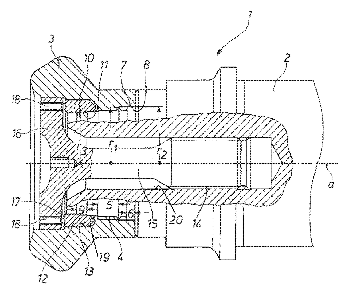
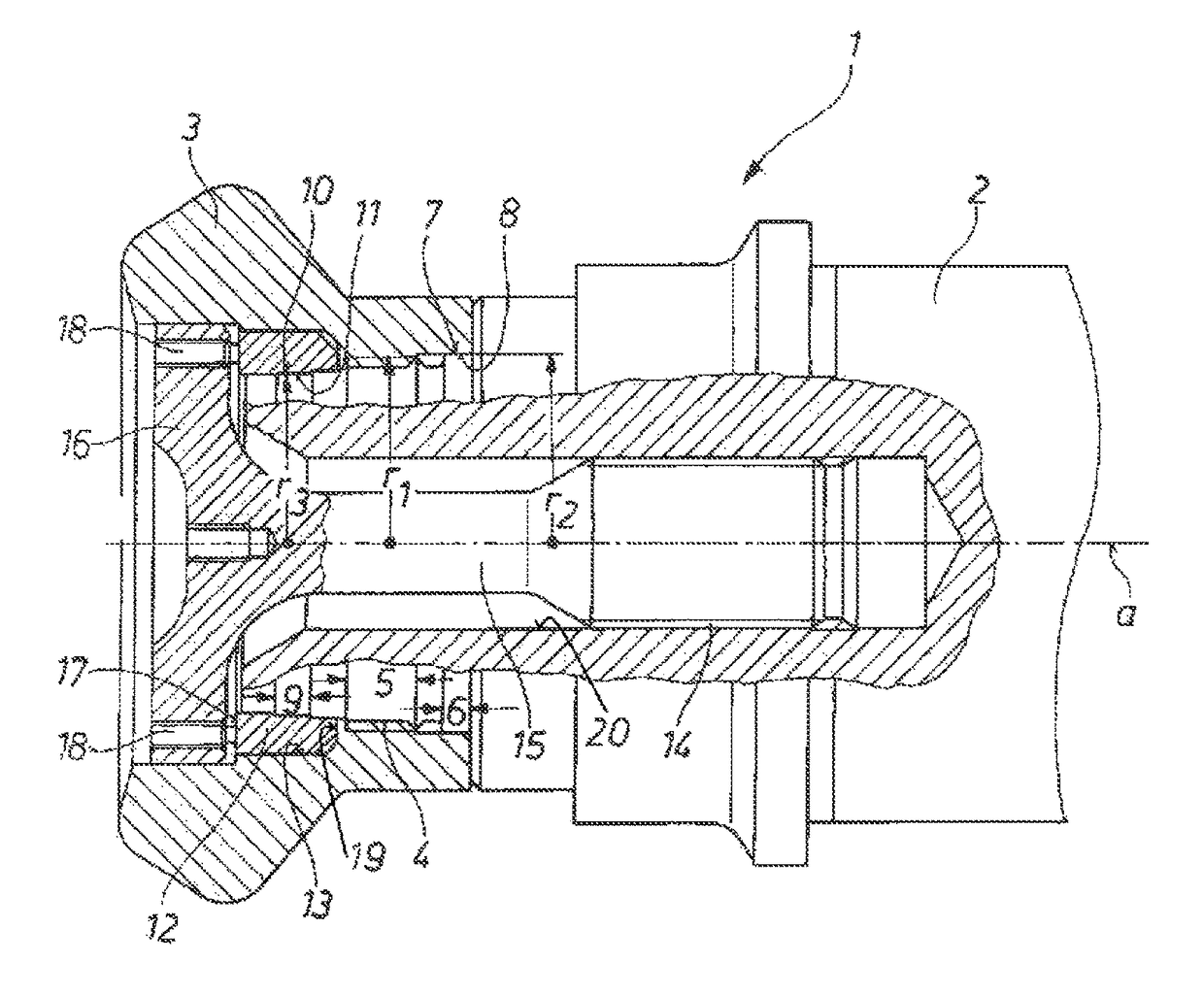
[0025]As seen in the drawing, an assembly 1 for shaping an unillustrated workpiece or rolled product comprises a steel drive shaft 2 that is centered on and that can rotate about an axis a and that is formed with an axially centered and outwardly open bore 20. A tool 3 in the form of a roll is attached to the axial outer end of drive shaft 2. The attachment is designed to be releasable, thereby allowing the tool 3, when worn, to be removed from the drive shaft 2 and replaced by a different one.

[0026]The drive shaft 2 and tool 3 are designed so that torque can be transmitted from the drive shaft 2 to the tool 3, and radial and axial forces can be also be transmitted relative to the axis a. The couplings are designed so that torque about the axis a and radial forces can be transmitted between the drive shaft 2 and the tool 3, and also so that axial forces can be transmitted between the drive shaft 2 and the tool 3, in each case separately and isolated from each other.

[0027]Specificall...


PUM

PropertyMeasurementUnit
torqueaaaaaaaaaa
diameteraaaaaaaaaa
radial forcesaaaaaaaaaa

Abstract

A workpiece-shaping tool assembly has a drive shaft having an outer end centered on and rotatable about an axis and a tool fittable with the end of the drive shaft. A torque coupling is formed by shaft splines formed on the drive shaft and tool splines formed on the tool, complementary to the shaft splines, and interfitting with the shaft splines. A radial-force coupling is formed by an inner cylindrical shaft surface formed on the shaft axially offset from the shaft splines and centered on the axis and a respective inner cylindrical tool surface formed on the tool offset from the tool splines, centered on the axis, and radially juxtaposed and engageable with the inner shaft surface.

Description

FIELD OF THE INVENTION[0001]The present invention relates to an workpiece-shaping tool assembly. More particularly this invention concerns a shaping roll.BACKGROUND OF THE INVENTION[0002]A typical workpiece-shaping assembly has a drive shaft centered on and rotatable about an axis and a tool, in particular, a roll, that is attached to this shaft. a keyed coupling, in particular a spline coupling, is provided between the drive shaft and the tool for transmitting torque from the drive shaft to the tool.[0003]Assemblies of this type involve releasably securing a tool, specifically, a roll, to the drive shaft. When in use, high torque must be transmitted by the drive shaft to the roll. A known approach here is to employ a spline coupling between drive shaft and roll. Involute spline couplings of this type are fairly well known and in common use. Reference is made here to DIN 5480 and DIN 5466 that provide information on the constructive design of these structures.[0004]The use of a spli...

Claims


Application Information

Patent Timeline
Patent Type & Authority Patents(United States)
IPC IPC(8): B21B35/14B21B13/00
CPCB21B35/14B21B35/141Y10T403/18B21B13/005B21D3/16B21B28/02B21D37/10B21D43/04
Inventor ESPOSITO, MICHAELLANGENOHL, ALJOSCHA
Owner SMS MEER
Learn More