
Radar sensor including a radome

a technology of radar sensor and radome, which is applied in the direction of reradiation, protective material radiating elements, instruments, etc., can solve the problem of significantly more severe attenuation of multiple reflections between printed circuit boards and bumpers, and achieve the effect of avoiding interference and reducing the number of attenuation

Active Publication Date: 2018-01-02
ROBERT BOSCH GMBH
View PDF22 Cites 2 Cited by
  • Summary
  • Abstract
  • Description
  • Claims
  • Application Information

AI Technical Summary

Benefits of technology

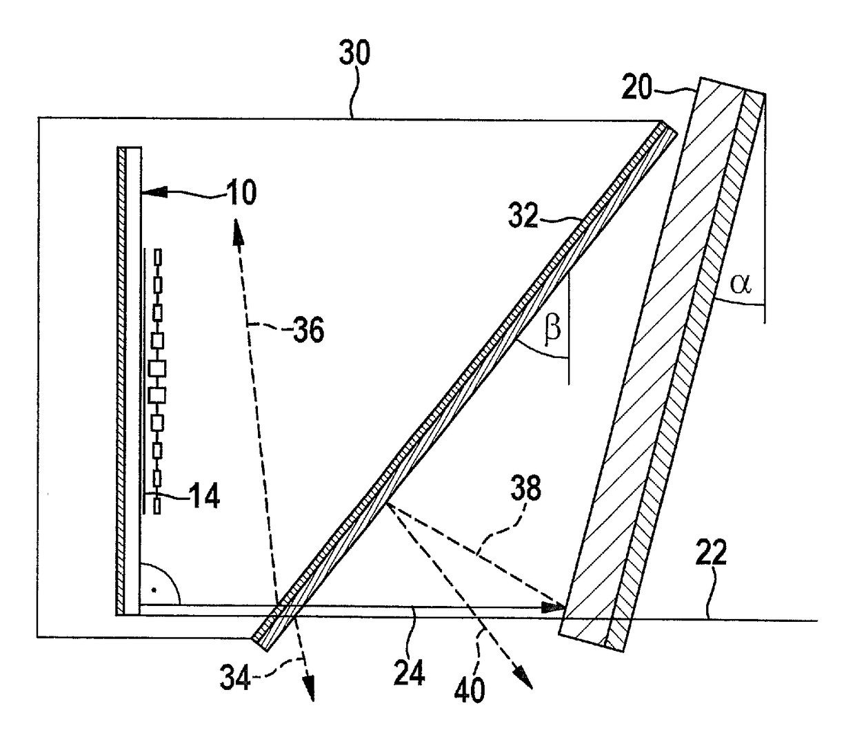
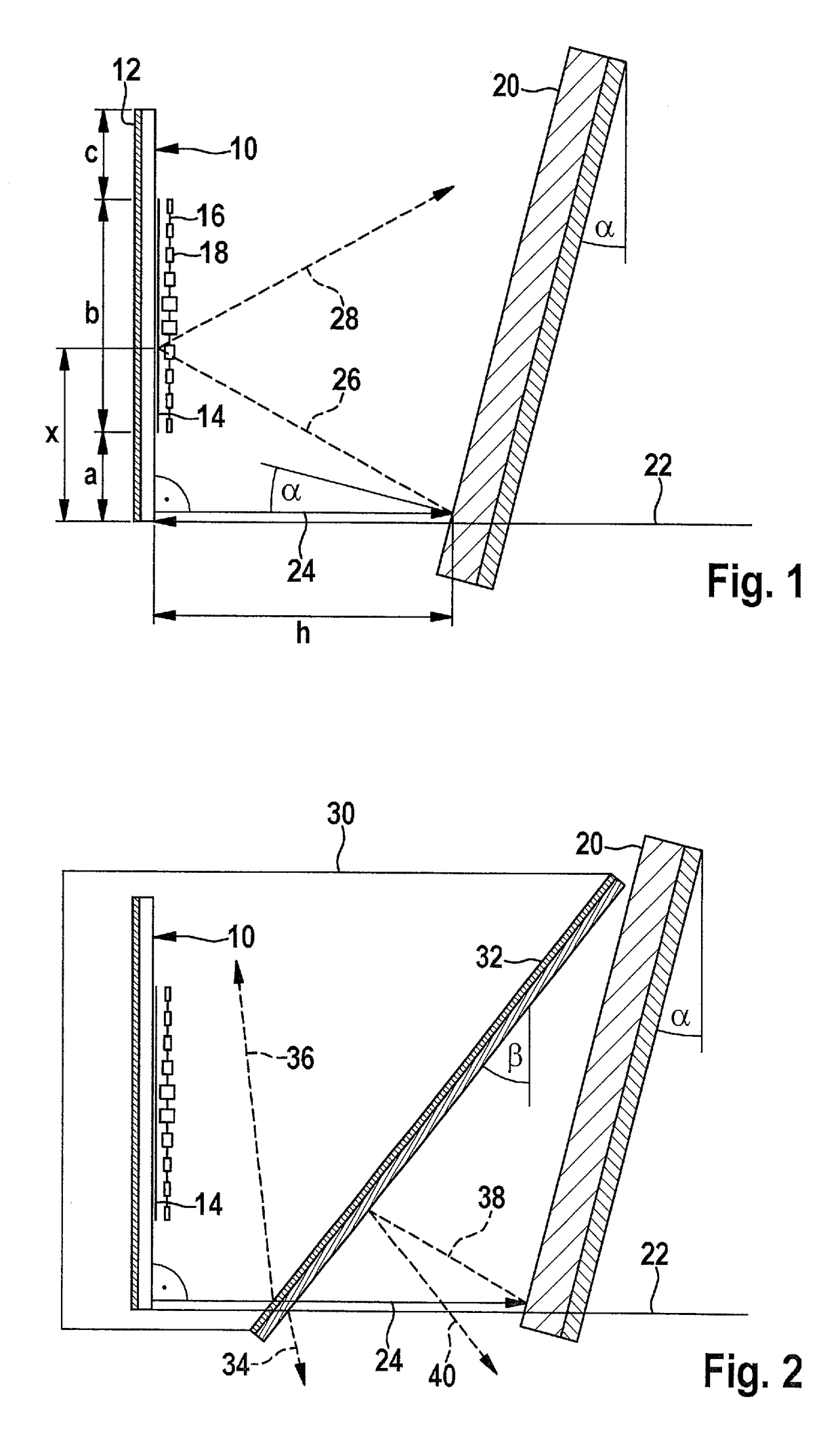
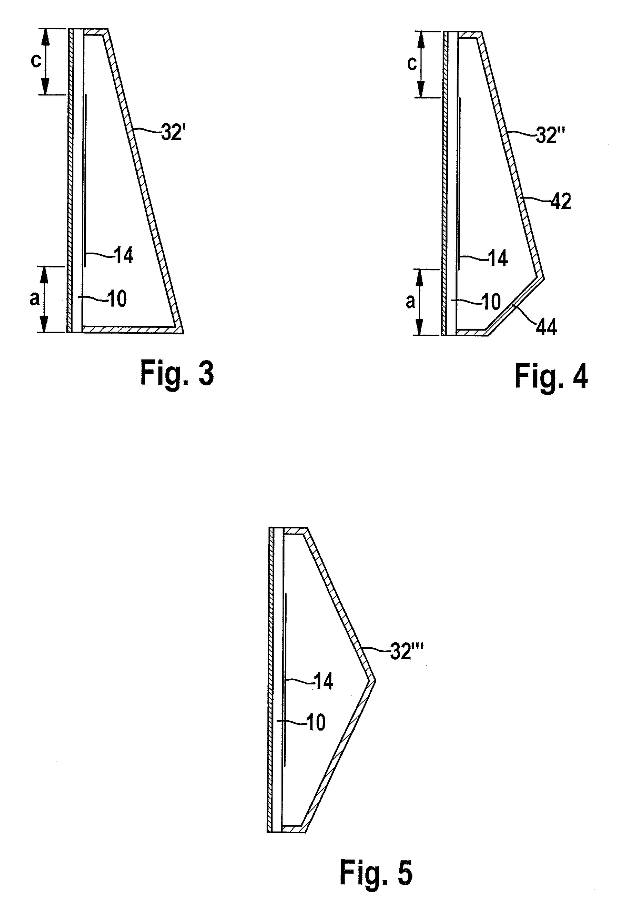
The present invention provides a radar sensor that is less sensitive to multiple reflections on the vehicle's bumper. This is achieved by having an oblique position of the radome, which causes the reflected waves to be deflected at an angle and no longer strike the antenna structures as early as after the first reflection, but no later than after the second or third reflection. This results in a relatively interference-free signal even when the bumper is not tilted or is tilted only slightly.

Problems solved by technology

Due to the additional reflection losses on the radome, the multiple reflections between the printed circuit board and the bumper are generally significantly more severely attenuated than in the case of a radar sensor whose radome is oriented in parallel to the printed circuit board.

Method used


Image

  • Radar sensor including a radome
  • Radar sensor including a radome
  • Radar sensor including a radome

Examples


Embodiment Construction

[0018]A side view of a printed circuit board 10 in the form of a plane plate of a radar sensor of a motor vehicle is shown schematically in FIG. 1, the printed circuit board being mounted in a vertical orientation in the front area of the motor vehicle, which is not shown. Printed circuit board 10 carries mass structures 12, which in the example shown have the form of a metallization on the rear side of the printed circuit board. Furthermore, on its front side, printed circuit board 10 carries antenna structures 14, for example, in the form of multiple vertical gaps 16 of antenna elements 18. A single one of these gaps 16 is shown schematically also in layout in FIG. 1.

[0019]Antenna elements 18 of each gap are connected in series to a high-frequency signal of an oscillator, which is not shown. The dimensions of antenna elements 18 and the distances between them are selected in such a way that the resonance vibrations excited in individual antenna elements 18 have phase and amplitude...


PUM


Abstract

A radar sensor for motor vehicles includes a printed circuit board which carries the mass and antenna structures of the radar sensor, and includes a housing accommodating the printed circuit board, the housing being formed on a transmit and receive side of the radar sensor by a radome which is transparent to radar radiation, characterized in that the radome has an essentially plane wall oriented obliquely to the printed circuit board.

Description

RELATED APPLICATION INFORMATION[0001]The present application claims priority to and the benefit of German patent application no. 10 2013 220 259.8, which was filed in Germany on Oct. 8, 2013, the disclosure of which is incorporated herein by reference.FIELD OF THE INVENTION[0002]The present invention relates to a radar sensor for motor vehicles, including a printed circuit board which carries the mass and antenna structures of the radar sensor, and including a housing accommodating the printed circuit board, the housing being formed on a transmit and receive side of the radar sensor by a radome which is transparent to radar radiation. The object of the present invention is moreover a motor vehicle having such a radar sensor.BACKGROUND INFORMATION[0003]Radar sensors are used in motor vehicles, for example, for measuring the distances and relative velocities of preceding vehicles, so that, for example, a collision warning and / or an automatic distance regulation is made possible. In th...

Claims


Application Information

Patent Timeline
Patent Type & Authority Patents(United States)
IPC IPC(8): H01Q1/42G01S13/02H01Q1/40G01S7/03G01S13/93G01S7/02H01Q1/32G01S13/931
CPCH01Q1/42G01S7/032G01S13/02G01S13/931H01Q1/40H01Q1/3233G01S7/02G01S2007/027G01S2013/9389G01S7/027G01S2013/93275
Inventor PONTES, JUAN
Owner ROBERT BOSCH GMBH
Learn More