
Intake assembly for an internal combustion engine

a technology of internal combustion engine and intake assembly, which is applied in the direction of combustion-air/fuel-air treatment, fuel-air cleaners, charge feed systems, etc., can solve the problems of development of intake ducts, and inability to achieve the desired effect, so as to improve the efficiency of the engine. , the effect of simple and efficient control of the engine operating conditions

Inactive Publication Date: 2017-12-19
CENT RICERCHE FIAT SCPA
View PDF8 Cites 0 Cited by
  • Summary
  • Abstract
  • Description
  • Claims
  • Application Information

AI Technical Summary

Benefits of technology

The invention provides an intake assembly for an engine that improves the efficiency of the intake ducts and makes it easy to control the engine's operating conditions.

Problems solved by technology

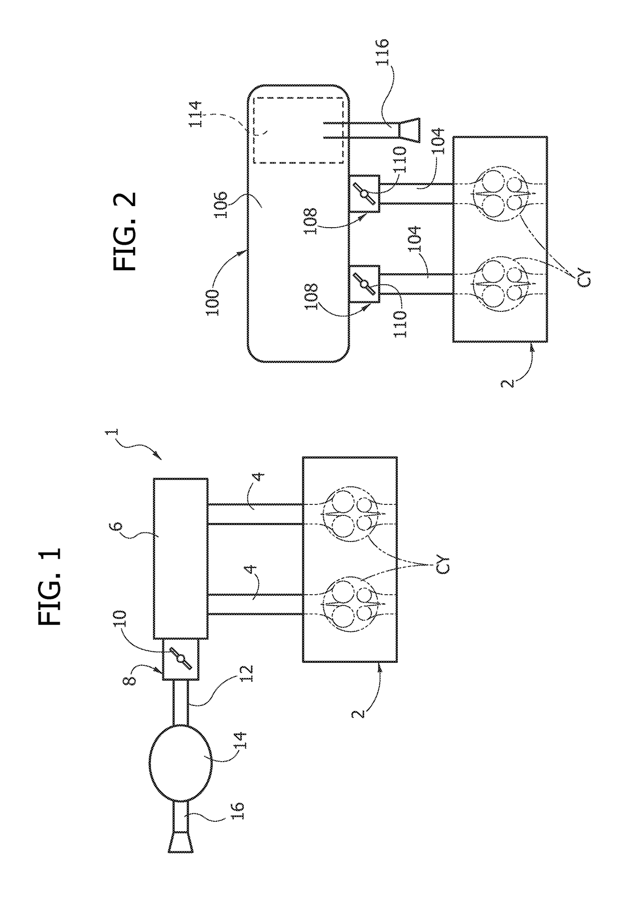
In a traditional system like the one represented in FIG. 1, the volume of the airbox 6 cannot be increased sufficiently to enable a satisfactory decoupling in so far as by so doing the volume of fluid “under throttle” (i.e., the volume of fluid comprised between the throttle body and the intake valves) would be too large, with the consequent unacceptable slowness in the dynamics of control of the air at inlet to the engine.
This is an evidently undesirable effect since the design effort for the development of intake ducts is in part nullified by a reduction of the volumetric efficiency of the internal-combustion engine 2, and hence of the torque supplied.

Method used


Image

  • Intake assembly for an internal combustion engine
  • Intake assembly for an internal combustion engine
  • Intake assembly for an internal combustion engine

Examples


Embodiment Construction

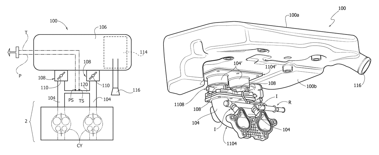
[0031]In FIG. 2, the reference number 100 designates an intake assembly according to various embodiments of the invention. Any components that may have already been identified in the foregoing description will be designated by the same reference numbers.

[0032]The intake assembly 100 can be coupled to the internal-combustion engine 2 and comprises, for each cylinder CY, an intake duct 104 in fluid communication with an airbox 106 by means of a throttle body 108. Each throttle body 108 comprises inside it a throttle valve 110.

[0033]Housed within the airbox 106 is a filter element 114, and an intake mouth 116 provided on the airbox 106 is directly in view of the aforesaid filter element 114 and is set upstream thereof and in fluid communication therewith. The intake mouth 116 may possibly be provided by means of a short stretch of duct coming under the airbox 106.

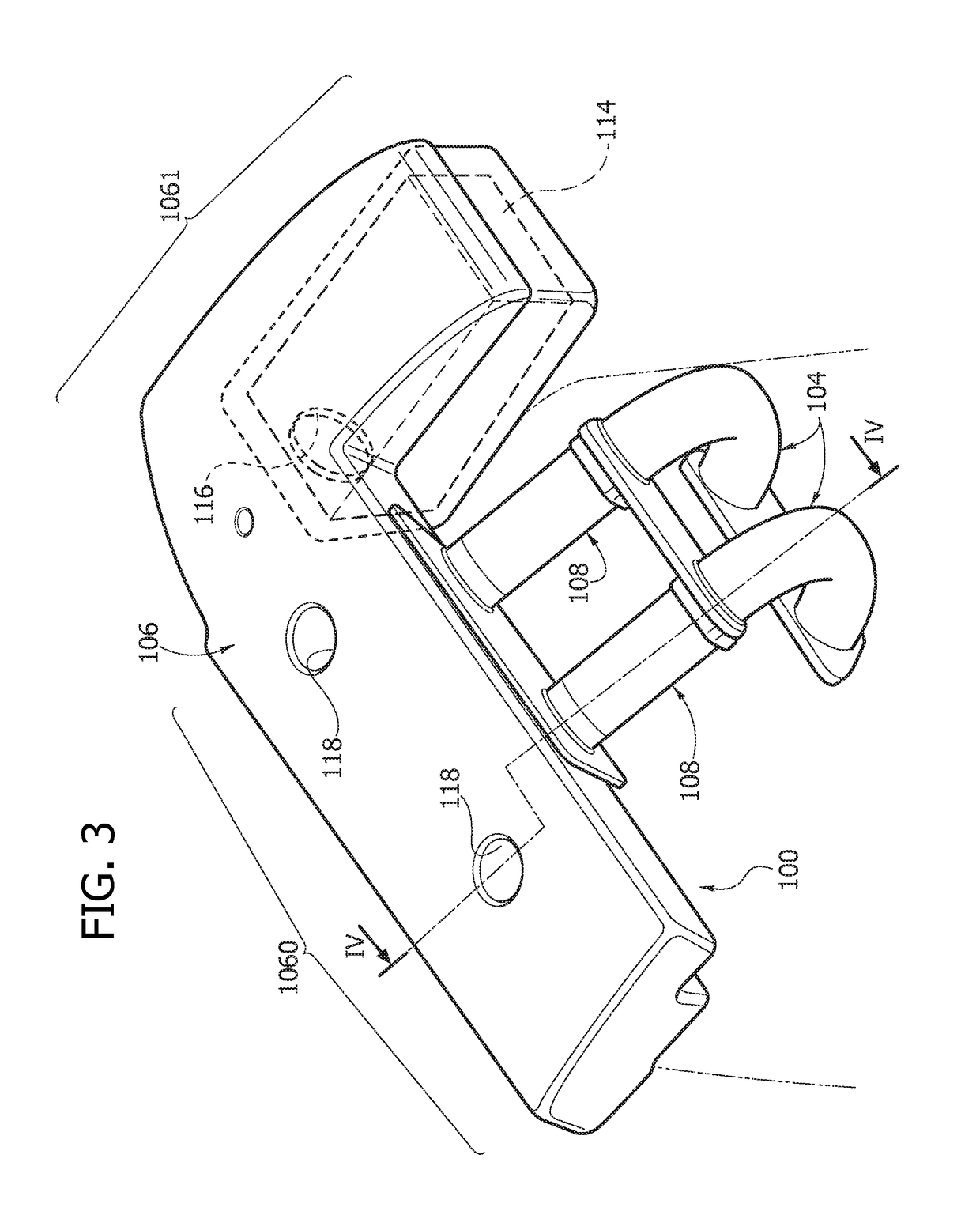
[0034]With reference to FIGS. 3, 4, in a preferred embodiment of the intake assembly 1, the airbox 106 develops with a subst...


PUM


Abstract

An intake assembly for an internal-combustion engine includes an intake duct for each cylinder, which communicates with an airbox that includes a filtering element. Each intake duct communicates with the airbox by a respective throttle body. A monitoring channel connects the intake ducts together and is configured for perturbing in a negligible way the dynamics of the fluid inside the intake ducts. Associated to said monitoring duct are sensors for monitoring the pressure inside the monitoring duct and designed to send signals indicating the value of pressure of the fluid taken in by the engine to an electronic control unit.

Description

CROSS-REFERENCE TO RELATED APPLICATIONS[0001]This application claims priority to European Patent Application No. 11186880.8 filed on Oct. 27, 2011 and European Patent Application No. 12180110.4 filed on Aug. 10, 2012, the entire disclosures of which are incorporated herein by reference.FIELD OF THE INVENTION[0002]The present description relates to an intake assembly for an internal-combustion engine with controlled ignition comprising a plurality of cylinders, wherein the intake assembly comprises an intake duct for each cylinder of the internal-combustion engine and an airbox defining a volume with which each intake duct is in fluid communication.GENERAL TECHNICAL PROBLEM[0003]In internal-combustion engines in which air is supplied by natural induction, i.e., without the aid of a supercharging assembly, it is common practice to resort to “tuning” of the intake ducts in order to maximize the volumetric efficiency of the engine in a particular r.p.m. range, chosen according to the us...

Claims


Application Information

Patent Timeline
Patent Type & Authority Patents(United States)
IPC IPC(8): F02M35/10F02M35/112F02M35/04F02D9/10F02M35/02
CPCF02M35/10308F02D9/109F02D9/1055F02D9/1095F02M35/0203F02M35/04F02M35/1038F02M35/10052F02M35/10072F02M35/10111F02M35/10255F02M35/112F02M35/044F02M35/048
Inventor CUNIBERTI, MARCOVATTANEO, FRANCESCOGALLONE, ALESSANDROGUZZI, LUIGINOVELLA, PAOLOVENEZIA, CATERINANASTRO, ROSARIO
Owner CENT RICERCHE FIAT SCPA
Learn More