
Vacuum circuit interrupter

a circuit interrupter and vacuum chamber technology, applied in the direction of air breakers, high-tension/heavy-dress switches, contacts heating/cooling, etc., can solve the problems of increased cost in that the operating mechanism must be robust, the stem has an expense related to its material cost, and the vacuum chamber is destroyed. , to achieve the effect of reducing length, less heat and less hea

Active Publication Date: 2017-12-12
EATON INTELLIGENT POWER LTD
View PDF17 Cites 10 Cited by
  • Summary
  • Abstract
  • Description
  • Claims
  • Application Information

AI Technical Summary

Benefits of technology

This patent describes a vacuum interrupter assembly that includes a mechanism, a vacuum chamber with bellows, and a conductor assembly with two contact assemblies. The first contact assembly has a stem with a contact member disposed in the vacuum chamber, while the second contact assembly has a stem and a contact member disposed in the vacuum chamber. The stem of the first contact assembly is designed to move between a first position where it is not directly coupled to the second contact assembly contact and a second position where it is coupled to the second contact assembly contact, and the stem of the first contact assembly has a reduced length which generates less heat and electrical resistance. The technical effect of this design is improved performance and reliability of the vacuum interrupter assembly.

Problems solved by technology

Thus, replacing the movable contact assembly, i.e., to change the operational characteristics of the vacuum circuit breaker, requires the destruction of the vacuum chamber.
That is, due to the mass of such stems, there is an increased cost in that the operating mechanism must be robust.
Further, such stems have an expense related to their material cost.
For example, larger electrodes are more expensive and require a more robust operating mechanism, which is also more expensive.
Further, a larger / more robust operating mechanism requires more energy to operate and is, therefore, more expensive to use as well.
If the elongated movable contact assembly stem was less massive, a less robust operating mechanism could be utilized.

Method used


Image

  • Vacuum circuit interrupter
  • Vacuum circuit interrupter
  • Vacuum circuit interrupter

Examples


Embodiment Construction

[0019]It will be appreciated that the specific elements illustrated in the figures herein and described in the following specification are simply exemplary embodiments of the disclosed concept, which are provided as non-limiting examples solely for the purpose of illustration. Therefore, specific dimensions, orientations, assembly, number of components used, embodiment configurations and other physical characteristics related to the embodiments disclosed herein are not to be considered limiting on the scope of the disclosed concept.

[0020]Directional phrases used herein, such as, for example, clockwise, counterclockwise, left, right, top, bottom, upwards, downwards and derivatives thereof, relate to the orientation of the elements shown in the drawings and are not limiting upon the claims unless expressly recited therein.

[0021]As used herein, the singular form of “a,”“an,” and “the” include plural references unless the context clearly dictates otherwise.

[0022]As used herein, the stat...


PUM


Abstract

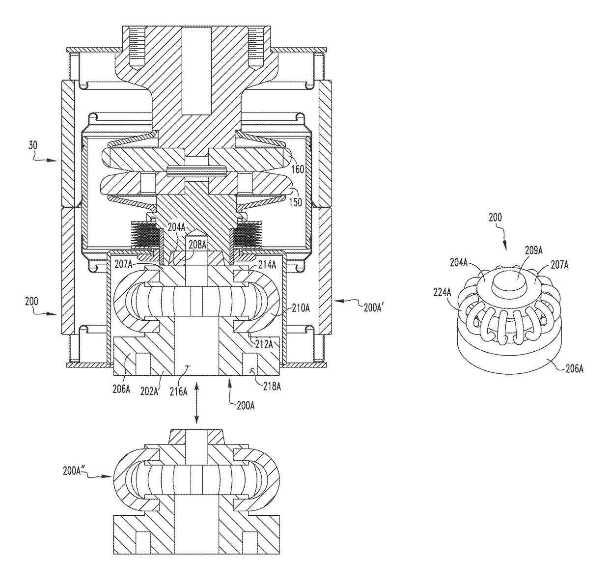
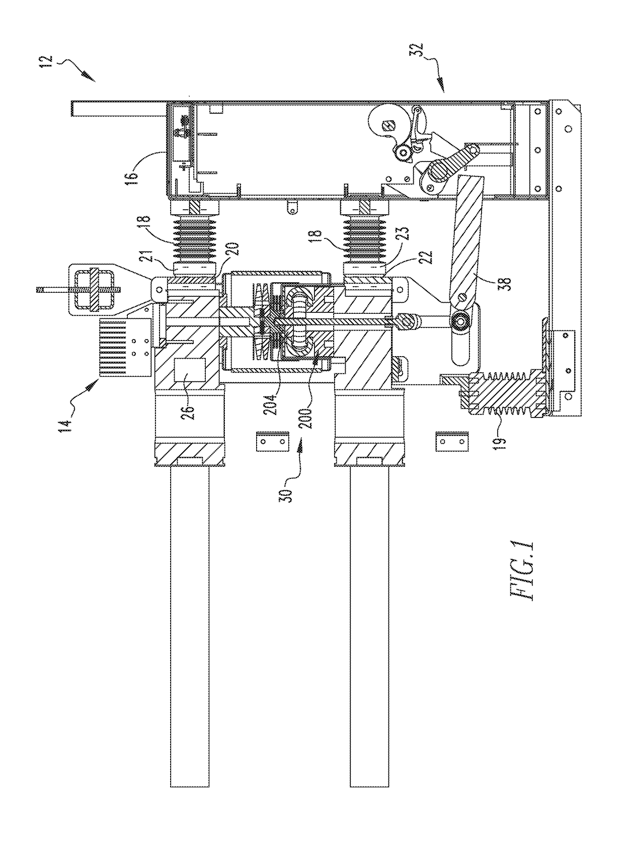
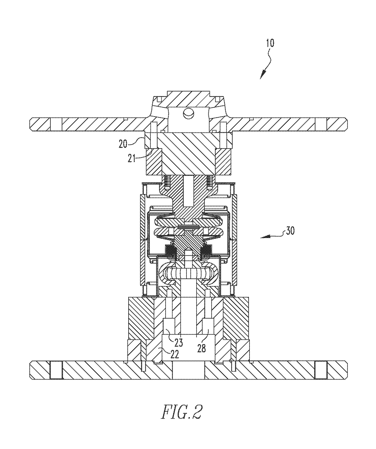
A vacuum interrupter assembly is provided. The vacuum interrupter assembly includes an operating mechanism, a vacuum chamber including a number of bellows assemblies, a conductor assembly including a first contact assembly and a second contact assembly, the first contact assembly including a stem and a contact member, the first contact assembly stem including an elongated body with a proximal first end, a medial portion, and a distal second end. The first contact assembly stem body has a reduced length. The first contact assembly stem body having a reduced length generates less heat and electrical resistance.

Description

BACKGROUND OF THE INVENTIONField of the Invention[0001]The disclosed and claimed concept relates to a vacuum circuit breaker and, more specifically, to a vacuum circuit breaker wherein a movable, first contact assembly stem body has a reduced length.Background Information[0002]Circuit breakers and other such devices provide protection for electrical systems from electrical fault conditions such as current overloads, short circuits, and low level voltage conditions. In one embodiment, circuit breakers include a spring-powered operating mechanism which opens electrical contacts to interrupt the current through the conductors in an electrical system in response to abnormal conditions. In particular, vacuum circuit interrupters include separable main contacts disposed within an insulated and hermetically sealed vacuum chamber within a housing. Generally, a movable contact assembly is welded to a bellows that is part of the vacuum chamber. Thus, replacing the movable contact assembly, i....

Claims


Application Information

Patent Timeline
Patent Type & Authority Patents(United States)
IPC IPC(8): H01H33/666H01H33/88
CPCH01H33/88H01H33/666H01H33/6606H01H33/664H01H1/62H01H2033/66253
Inventor YU, LILEUSENKAMP, MARTIN BERNARDUS JOHANNESYANG, HEHOU, WENJIELI, YUCHENGYAN, JUN
Owner EATON INTELLIGENT POWER LTD
Learn More