
Bearing with drained race and squeeze film damper

a technology of squeeze film and outer race, which is applied in the direction of elastic bearings, machines/engines, rigid support of bearings, etc., can solve the problems of vibration and dynamic loads on shafts, and the combination of drained outer race and typical dual piston ring squeeze film damper is problemati

Active Publication Date: 2017-12-12
GENERAL ELECTRIC CO
View PDF18 Cites 25 Cited by
  • Summary
  • Abstract
  • Description
  • Claims
  • Application Information

AI Technical Summary

Benefits of technology

This design allows for the simultaneous reduction of dynamic loads and heat generation in gas turbine engines by maintaining the benefits of both drained outer races and squeeze film dampers within the same bearing volume, enhancing operational stability and efficiency.

Problems solved by technology

In operation, the shafts are subject to vibration and dynamic loads caused by rotor and shaft unbalance and by self-excited whirl (i.e. dynamic instability).
Combining a drained outer race with a typical dual piston ring squeeze film damper would be problematic because the circumferential oil film would interfere with the bearing oil drain holes.

Method used


Image

  • Bearing with drained race and squeeze film damper
  • Bearing with drained race and squeeze film damper
  • Bearing with drained race and squeeze film damper

Examples


Embodiment Construction

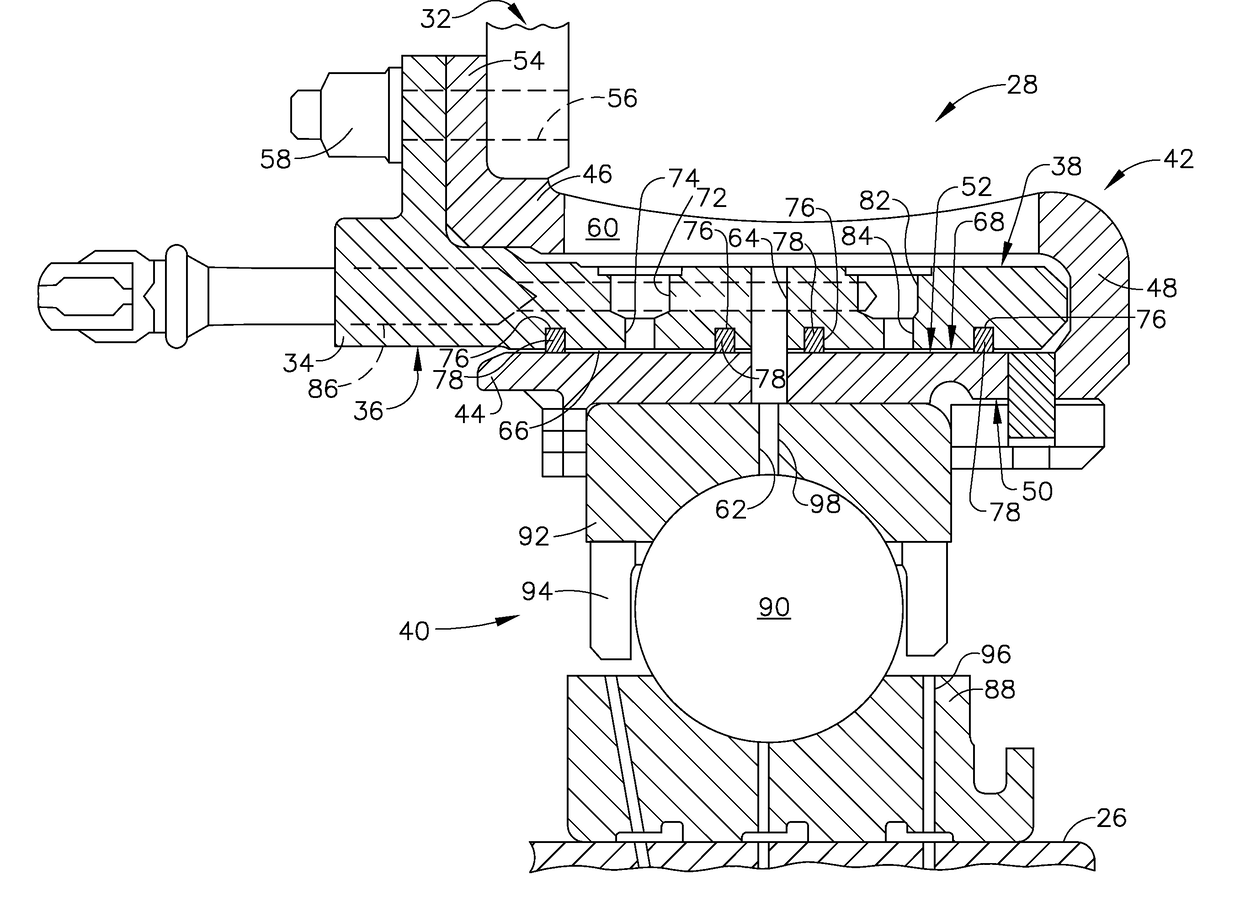
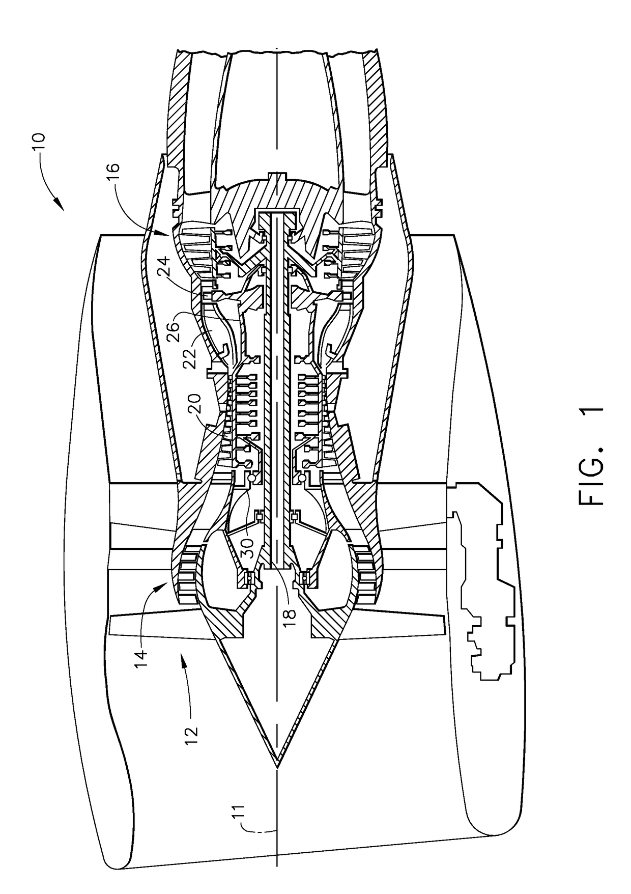
[0012]Referring to the drawings wherein identical reference numerals denote the same elements throughout the various views, FIG. 1 depicts a gas turbine engine 10. The engine 10 has a longitudinal axis 11 and includes a fan 12, a low pressure compressor or “booster”14 and a low pressure turbine (“LPT”) 16 collectively referred to as a “low pressure system”.

[0013]It is noted that, as used herein, the terms “axial” and “longitudinal” both refer to a direction parallel to the centerline axis 11, while “radial” refers to a direction perpendicular to the axial direction, and “tangential” or “circumferential” refers to a direction mutually perpendicular to the axial and tangential directions. As used herein, the terms “forward” or “front” refer to a location relatively upstream or forward in the engine 10, and the terms “aft” or “rear” refer to a location relatively downstream or rearward in the engine 10. These directional terms are used merely for convenience in description and do not r...


PUM


Abstract

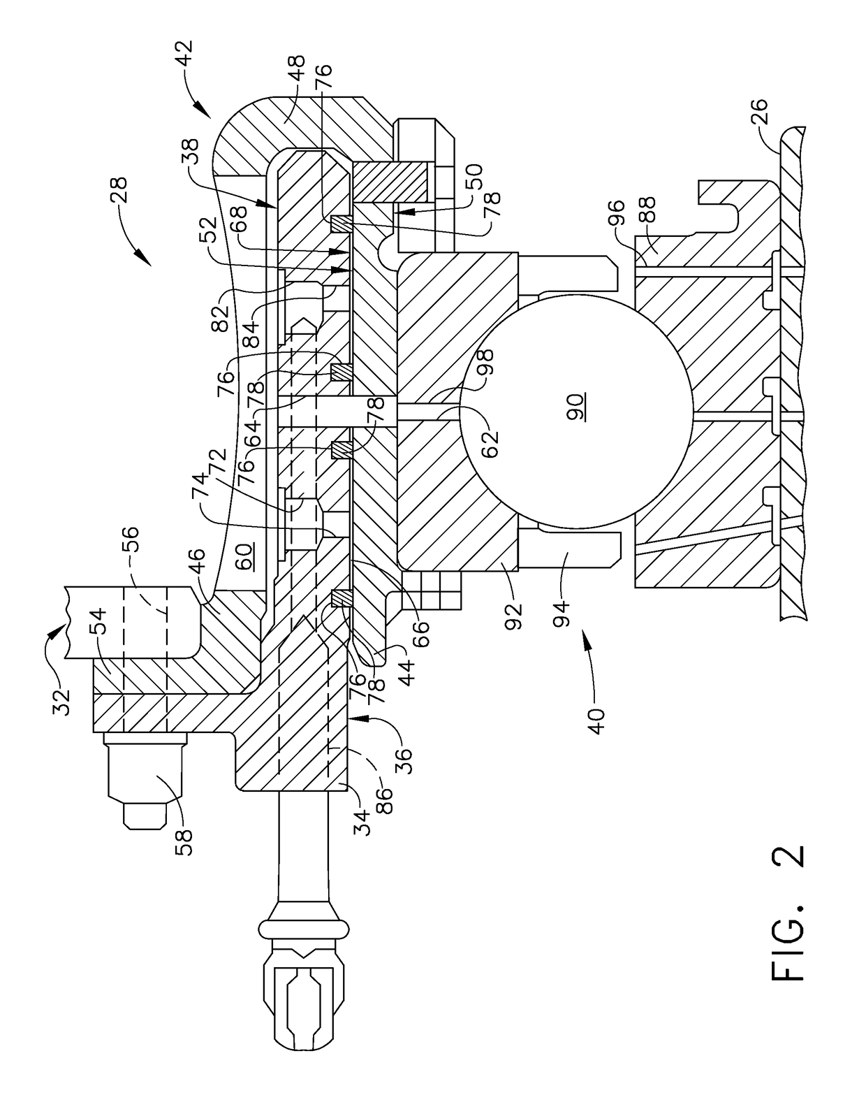
A bearing apparatus includes: a bearing including a first race rotatable relative to a second race, wherein the first race includes one or more drain passages extending therethrough; and a squeeze film damper connected to the first race, the squeeze film damper including first and second squeeze film spaces separated by an oil drain path which communicates with the one or more drain passages of the first race.

Description

STATEMENT REGARDING FEDERALLY SPONSORED RESEARCH AND DEVELOPMENT[0001]The U.S. Government may have certain rights in this invention pursuant to contract no. FA8650-09-D-2922 awarded by the Department of the Air Force.BACKGROUND OF THE INVENTION[0002]This invention relates generally to rolling element bearings and more particularly to the mounting of such bearings in gas turbine engines.[0003]A gas turbine engine includes one or more shafts which are mounted for rotation in several bearings, usually of the rolling-element type. The bearings are enclosed in enclosures called “sumps” which are pressurized and provided with an oil flow for lubrication and cooling. The bearings in a gas turbine engine are usually a combination of roller and ball bearings. The roller bearings react radial loads of the shafts and the ball bearings react radial and thrust loads.[0004]In operation, the shafts are subject to vibration and dynamic loads caused by rotor and shaft unbalance and by self-excited w...

Claims


Application Information

Patent Timeline
Patent Type & Authority Patents(United States)
IPC IPC(8): F16C33/66F01D25/18F16C27/04F16C35/04F16C19/16F01D25/16F16C19/06
CPCF16C33/6685F01D25/162F01D25/18F16C19/16F16C27/045F16C33/6659F16C35/045F16C2360/23F05D2220/32F05D2240/54F05D2260/96F16C19/06F16C33/6677
Inventor SNOW, KYLE ROBERTOGSTON, PHILIP J.GRADY, CHRISTOPHER MICHAEL
Owner GENERAL ELECTRIC CO
Learn More