
Personalized tourniquet apparatus

a technology of tourniquets and equipment, which is applied in the field of pneumatic tourniquet systems, can solve the problems of high risk of tourniquet-related injuries to patients, sensor requirements, and disruption of pre-surgical workflow

Active Publication Date: 2017-11-14
WESTERN CLINICAL ENG
View PDF36 Cites 2 Cited by
  • Summary
  • Abstract
  • Description
  • Claims
  • Application Information

AI Technical Summary

Benefits of technology

This patent is about a pneumatic tourniquet system commonly used in surgery to stop the penetration of arterial blood into a patient's limb for a surgical procedure. The invention is about a new pneumatic tourniquet system that can establish and maintain a personalized tourniquet pressure for surgery, based on the minimum pressure required to stop arterial blood flow past a specific cuff applied to a specific patient's limb at a specific location. This new system takes into account variables such as patient's limb characteristics, cuff design, and physiologic characteristics of the patient, to ensure the safest and most effective tourniquet pressure for surgery. The technical effect of this invention is to provide a more effective and safe pneumatic tourniquet system for surgery.

Problems solved by technology

Tourniquet cuffs of the prior art are not designed to serve a sensing purpose, and blood-pressure cuffs of the prior art are not designed to serve an effector purpose.
Such studies have shown that higher tourniquet pressures are associated with higher risks of tourniquet-related injuries to the patient.
Despite the improved performance of prior-art apparatus that automatically measures LOP, there are three significant limitations.
The first limitation is that a separate, complex and costly distal flow sensor is required: the correct application and use of the required distal sensor for automatic LOP measurement is dependent on the skill, training and experience of the surgical staff; the sensor must be located distally on the limb undergoing surgery and this may not be possible in some instances; in other instances the distal location of the sensor requires placement of a non-sterile sensor in or near a sterile surgical field and interferes with the pre-surgical preparation of the limb, thus disrupting the pre-surgical workflow and undesirably increasing the overall perioperative time and costs.
A second limitation is that the apparatus of the prior art does not measure or estimate any changes to LOP that may occur during surgery.
The third limitation is that the Recommended Tourniquet Pressure (RTP) is not a personalized tourniquet pressure (PTP) for that individual patient, and instead is a population estimate equaling the sum of the LOP measured at some time pre-surgically plus a population-based and predetermined increment of pressure.
Such prior-art apparatus is impractical because blood must flow past the tourniquet cuff before it can be detected, requiring surgical staff to do one of two things if blood enters the surgical field: interrupt the surgical procedure and take action to remove the blood; or proceed with blood in the field which might affect visualization and the quality of surgery.
Such apparatus can only be used when arterial blood is actually flowing past the tourniquet cuff toward the surgical field.
Ultrasonic tourniquet systems of the prior art have other significant limitations: the additional ultrasonic sensing arrays required, together with the associated ultrasonic signal processing circuitry and software, are costly; also, adapting and incorporating ultrasonic sensing arrays into tourniquet cuffs is complex and costly, and may be prohibitive in view of the fact that competing tourniquet systems employ cuffs that are sterile, low-cost, disposable products; further, the safe operation of ultrasonic tourniquet systems is at present complex and user-dependent, requiring additional user training and skill.

Method used


Image

  • Personalized tourniquet apparatus
  • Personalized tourniquet apparatus
  • Personalized tourniquet apparatus

Examples


Embodiment Construction

[0020]The embodiments illustrated are not intended to be exhaustive or limit the invention to the precise form disclosed. They are chosen and described in order to explain the principles of the invention and its application and practical use, and thereby enable others skilled in the art to utilize the invention.

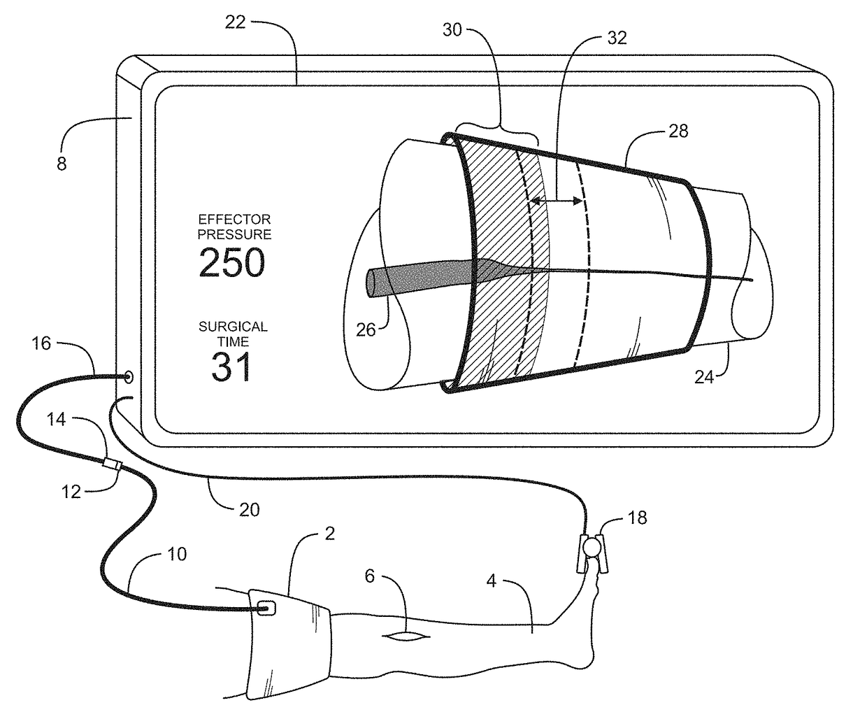
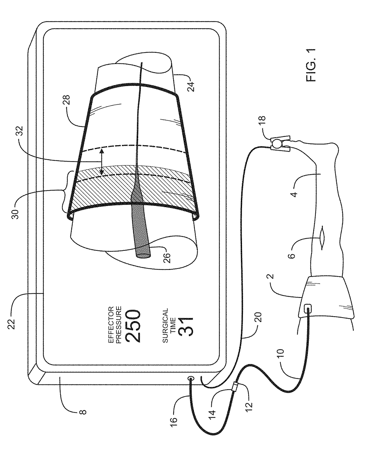
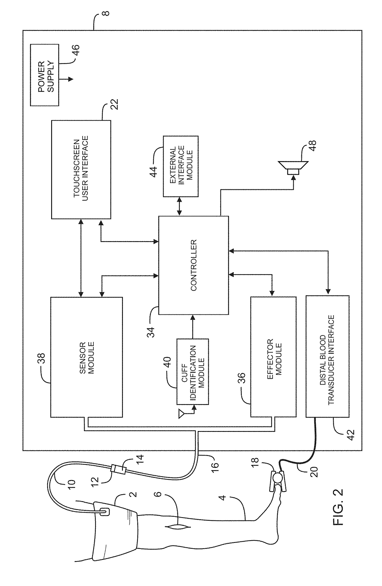
[0021]FIG. 1 depicts the tourniquet system of a preferred embodiment in clinical use. Tourniquet cuff 2 is shown encircling a patient limb 4 at a location proximal to surgical site 6 and pneumatically connected to instrument 8. Cuff 2 is a dual-purpose tourniquet cuff that effects the stoppage of blood penetration past the cuff when inflated and senses changes in blood penetration in the portion of the limb encircled by the cuff when blood penetration past the cuff is stopped.

[0022]Cuff 2 is a type of tourniquet cuff that has common predetermined parameters that makes it suitable as a dual-purpose cuff including: a single inflatable bladder having a length sufficient to surro...


PUM


Abstract

Disclosed is a method and apparatus for regulating tourniquet cuff pressure based on a personalized tourniquet pressure (PTP) to facilitate safe performance of a surgical procedure. The apparatus includes a dual-purpose tourniquet cuff adapted to encircle a region of a patient limb to provide both a sensor during a pre-surgical time period and an effector during a surgical time period. An effector module communicates pneumatically with an inflatable bladder of the cuff for maintaining pressure in the bladder near a PTP during the surgical time period to safely stop penetration of arterial blood past the cuff. A pulsation sensor that communicates pneumatically with the inflatable bladder during the pre-surgical time period senses and characterizes pressure pulsations that are indicative of penetration of arterial blood into the region of the limb encircled by the cuff. A PTP estimator is responsive to the pulsation sensor for producing an estimate of the PTP, such that the estimate of the PTP is a function of the sensed pulsations.

Description

FIELD OF THE INVENTION[0001]This invention pertains to pneumatic tourniquet systems commonly used for stopping the penetration of arterial blood into a portion of a surgical patient's limb to facilitate the performance of a surgical procedure. In particular, this invention pertains to a pneumatic tourniquet apparatus for establishing and maintaining a personalized tourniquet pressure for surgery.BACKGROUND OF THE INVENTION[0002]Surgical tourniquet systems are commonly used to stop the penetration of arterial blood into a portion of a patient's limb, thus creating a clear, dry surgical field that facilitates the performance of a surgical procedure and improves outcomes. A typical surgical tourniquet system of the prior art includes a tourniquet cuff for encircling a patient's limb at a desired location, a tourniquet instrument, and flexible tubing connecting the cuff to the instrument. In some surgical tourniquet systems of the prior art, the tourniquet cuff includes an inflatable bl...

Claims


Application Information

Patent Timeline
Patent Type & Authority Patents(United States)
IPC IPC(8): A61B17/00A61B17/135A61B90/98A61B90/92A61B5/022A61B90/00A61B17/132
CPCA61B17/1355A61B5/02233A61B5/022A61B17/132A61B17/135A61B17/1322A61B2505/05A61B90/98A61B2017/00017A61B2017/00022A61B2017/00119A61B2017/00199A61B2090/0807A61B90/92
Inventor MCEWEN, JAMES A.JAMESON, MICHAELJEYASURYA, JESWINGLINZ, KENNETH L.
Owner WESTERN CLINICAL ENG
Learn More