
Slot motor configuration for high amperage multi-finger circuit breaker

a multi-finger, circuit breaker technology, applied in the direction of circuit-breaking switch contacts, circuit-breaking switch details, high-tension/heavy-dress switches, etc., can solve the problems of reducing the options available to designers, requiring a large width direction of the circuit breaker, and reducing the range of circuit breakers, so as to prevent excessive heat energy from accumulating, prolong the circuit breaker, and accelerate the arc

Active Publication Date: 2017-10-31
SIEMENS AG
View PDF10 Cites 2 Cited by
  • Summary
  • Abstract
  • Description
  • Claims
  • Application Information

AI Technical Summary

Benefits of technology

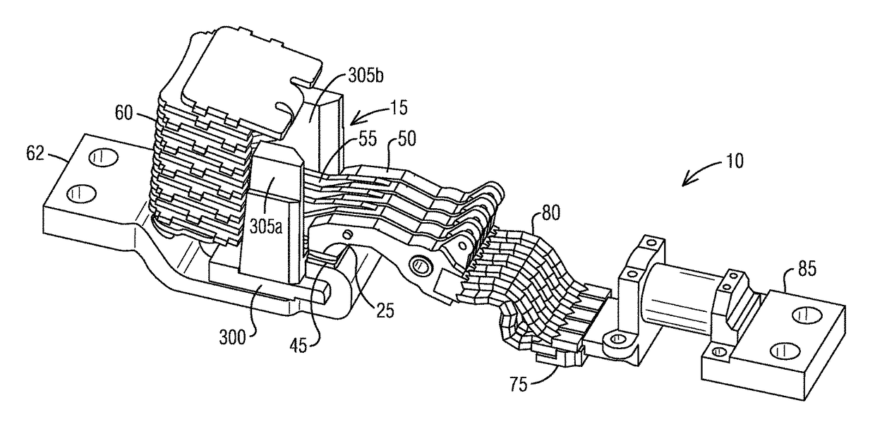
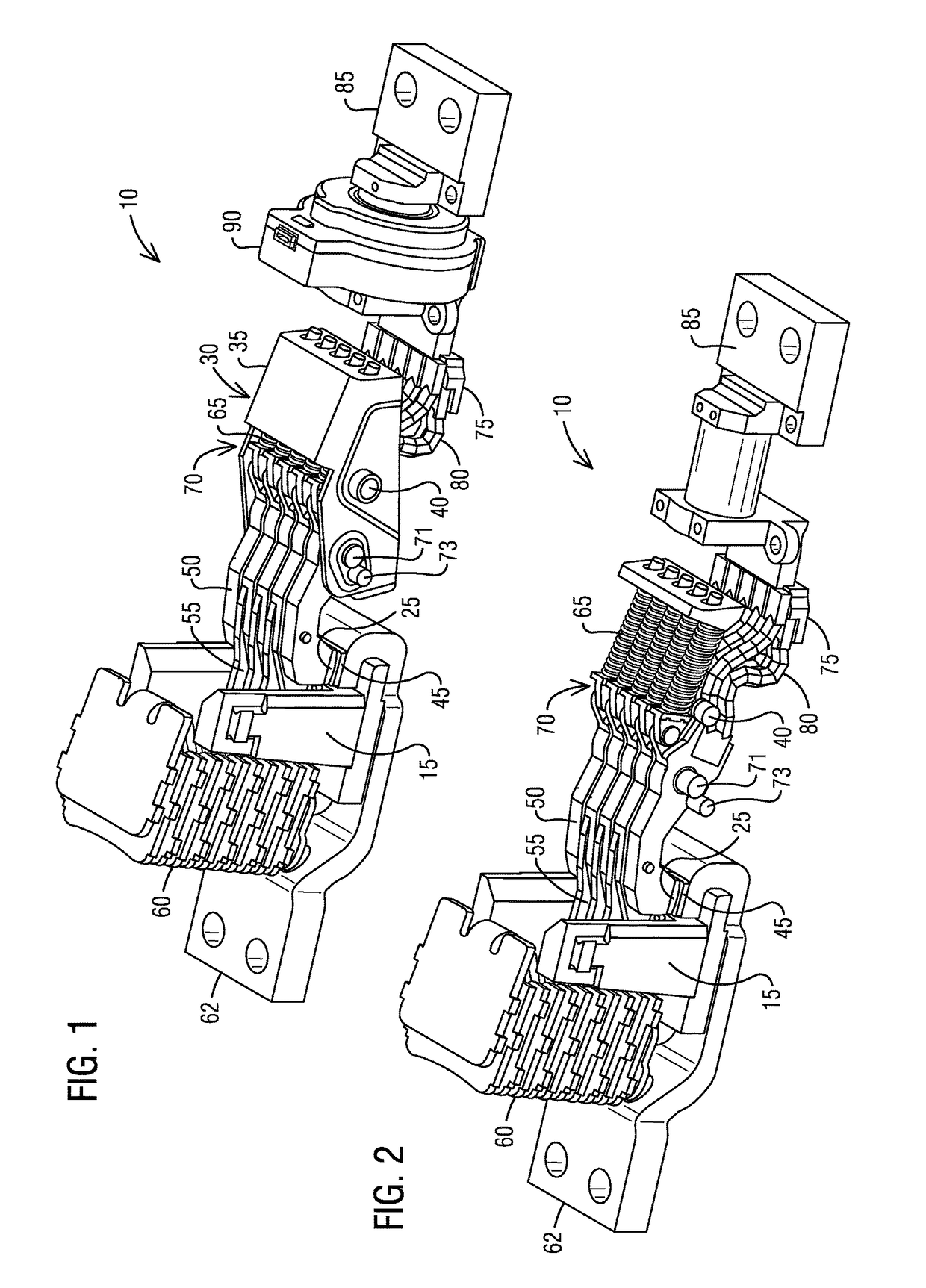
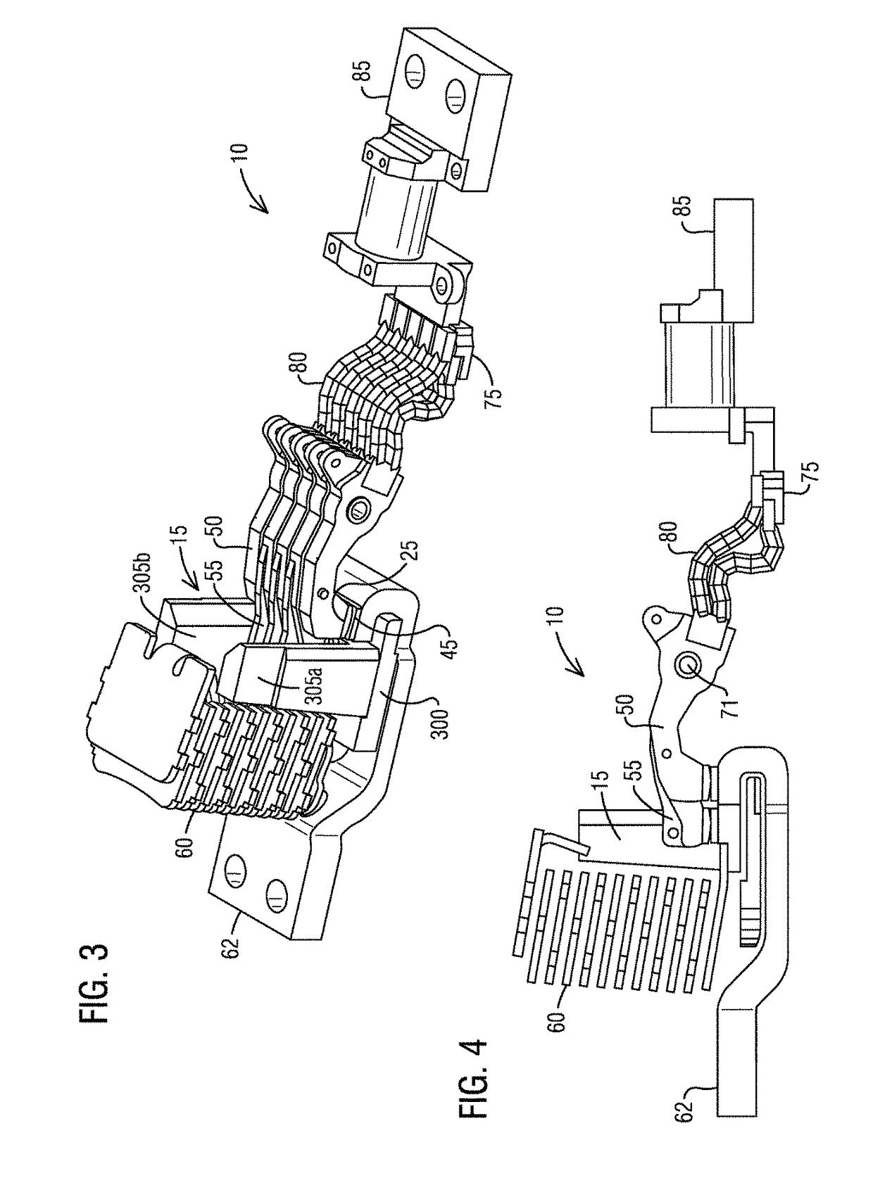
The present invention relates to using a slot motor to quickly move a short circuit arc away from the breaking contacts of a circuit breaker and prevent excessive heat energy from accumulating. This is achieved by replacing the splitter plate side extensions with a slot motor that amplifies the magnetic forces on the long fingers. A plurality of magnetic steel splitter plates also contribute and assist in amplifying the magnetic field. The slot motor can be installed in a multi-finger circuit breaker and is particularly useful in high amperage circuit breakers with both short and long fingers present.

Problems solved by technology

A particular problem arises in larger circuit breakers with continuous current ratings of about 600 A and greater.
However, much space in the width direction of the breaker is required to accommodate the multiple contact fingers and large copper cross-sections.
This takes away from the options available to the designer for increasing arc force during short circuit interruption.
However, if there are multiple fingers side-by-side, there is not the room for these solutions that work in smaller breakers.
Adding additional width to the breaker is usually undesirable because it increases overall size.
But furthermore, increasing width has only limited benefit for improving arc force.
Outgassing plastic is less effective, because the exposed surface area is a smaller proportion compared to the arcing volume.
Therefore the problem is how to generate a strong force to move the short circuit arc away from between the breaking contacts, in large MCCBs or ACBs rated approximately 800 A or greater with more than 3 contact fingers.
This is because the higher voltage tends to increase the heating and duration of the arc, and the relatively low short circuit current means it is more difficult to generate strong magnetic forces.
Some devices either offer no short circuit rating at the higher voltages, or else they offer very low current ratings at higher voltages to keep arc energy below the level that would create so much heat that the arc cannot be extinguished.
But this solution allows the arc to burn for a relatively long time because there is not much enhancement of the arc force.
In a short circuit there are magnetic repulsive forces that tend to blow the contact fingers open.
However, this concept of short and long fingers with the splitter plate side extensions also has several operational disadvantages.

Method used


Image

  • Slot motor configuration for high amperage multi-finger circuit breaker
  • Slot motor configuration for high amperage multi-finger circuit breaker
  • Slot motor configuration for high amperage multi-finger circuit breaker

Examples


Embodiment Construction

[0033]To facilitate an understanding of embodiments, principles, and features of the present invention, they are explained hereinafter with reference to implementation in illustrative embodiments. In particular, they are described in the context of being a slot motor disposed adjacent a plurality of short fingers and at least one long finger to amplify a magnetic field force being applied on the long finger in a multi-finger circuit breaker. For example, such a magnetic field force pulls an arc that develops on all of a plurality of movable contacts from the plurality of short fingers to the long finger when opening the plurality of movable contacts of a pole of the multi-finger circuit breaker during a short circuit. Embodiments of the present invention, however, are not limited to use in the described devices or methods.

[0034]The components and materials described hereinafter as making up the various embodiments are intended to be illustrative and not restrictive. Many suitable co...


PUM


Abstract

A multi-finger circuit breaker includes a moving contact assembly having a carrier body, a first plurality of fixed breaking contacts, a first plurality of movable contacts, a plurality of first fingers, at least one second finger longer in length to a length of a first finger of the plurality of first fingers, a plurality of splitter plates disposed adjacent to the plurality of first fingers and the at least one second finger and a slot motor disposed adjacent to the plurality of first fingers and the at least one second finger. The slot motor is configured to provide a first magnetic field force to amplify a second magnetic field force being applied on the second finger to influence an arc between the first plurality of fixed breaking contacts and the first plurality of movable contacts during a short circuit such that to move the arc away from between the first plurality of fixed breaking contacts and the first plurality of movable contacts and dissipate energy of the arc.

Description

BACKGROUND1. Field[0001]Aspects of the present invention generally relate to circuit breakers and more specifically relate to configuring a slot motor to generate a sufficient magnetic field force to move a short circuit arc away from between the breaking contacts for extinguishing it quickly to prevent excessive heat energy from accumulating in multi-finger circuit breakers.2. Description of the Related Art[0002]Any molded case circuit breaker (MCCB) or air circuit breaker (ACB) must be able to interrupt short circuits at the various circuit levels for which it is rated. At the short circuit levels of MCCBs and ACBs, a short circuit arc will continue to burn between the contacts unless some means is provided to move the arc away from between the contacts for dissipating its energy. Typically magnetic forces and gas flow arising from the expanding gases are exploited to move the arc, causing it to lengthen and also move into a set of arc splitter plates. Lengthening increases the re...

Claims


Application Information

Patent Timeline
Patent Type & Authority Patents(United States)
IPC IPC(8): H01H33/10
CPCH01H33/10H01H2235/01H01H2205/002H01H73/04H01H73/18H01H9/345H01H9/40H01H9/446
Inventor FERREE, JAMES EDWARD
Owner SIEMENS AG
Learn More