Accessory assembly of bicycle and mounting device of the accessory assembly

a technology of accessory assembly and accessory rod, which is applied in the direction of steering device, other supporting device, cycle equipment, etc., can solve the problems of insufficient room and inconvenient control of the control rod, and achieve the effect of convenient use and convenient us

Active Publication Date: 2017-10-03
LEE CHI ENTERPRISES
View PDF49 Cites 0 Cited by
  • Summary
  • Abstract
  • Description
  • Claims
  • Application Information

AI Technical Summary

Benefits of technology

[0008]The primary objective of the present invention is to provide an accessory assembly and a securing device thereof, which mounts accessories on a handlebar of a bicycle in a radial direction of the handlebar to effectively save spaces on the handlebar in an axial direction thereof.
[0009]According to the objective of the present invention, the present invention provides a mounting frame connected to a handlebar of a bicycle for mounting accessories thereon. The mounting frame includes a central hole and a plurality of coupling slots. The central hole allows the handlebar to be inserted thereinto, and the coupling slots are provided on a surface of the mounting frame in different radial directions of the central hole. The coupling slots each have an elongated direction, which is substantially parallel to an axial direction of the central hole. Each of the coupling slots allows a bicycle accessory to be engaged therewith.
[0013]Whereby, bicycle accessories can be arranged in different radial directions of the handlebar. Therefore the space on the handlebar in an axial direction thereof is saved, and the handlebar is able to engage more bicycle accessories.

Problems solved by technology

But even so, for a rider who has shorter fingers, it would be inconvenient to control the control rods which are farther from the handles.
These accessories, such as lights, warning lights, bells, cell phone holders, satellite navigators, etc., are typically designed to be attached onto the handlebar of a bicycle, but there might not be enough room for them.

Method used


Image

  • Accessory assembly of bicycle and mounting device of the accessory assembly
  • Accessory assembly of bicycle and mounting device of the accessory assembly
  • Accessory assembly of bicycle and mounting device of the accessory assembly

Examples


Embodiment Construction

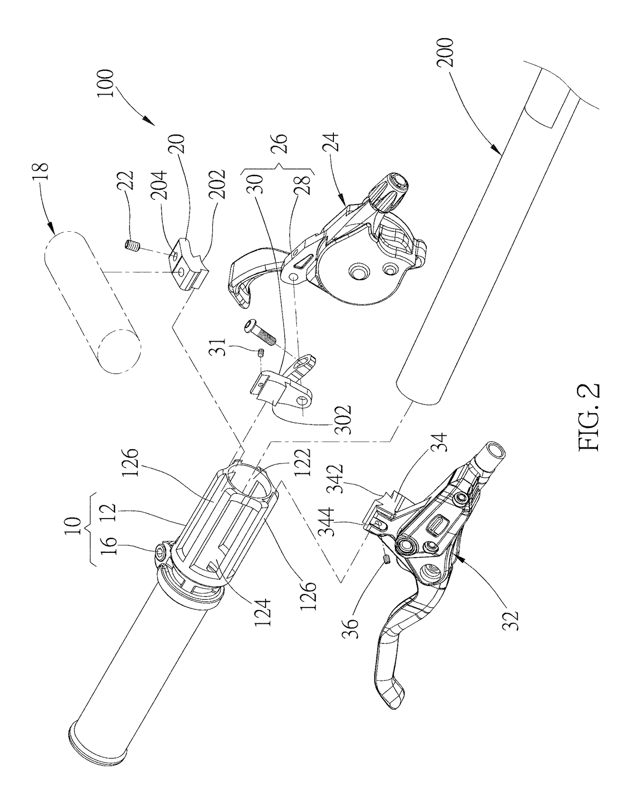
[0025]As shown in FIG. 1 and FIG. 2, an accessory assembly 100 of the preferred embodiment of the present invention is mounted on a handlebar 200 of a bicycle (not shown). The accessory assembly 100 includes a mounting frame 10 and a plurality of accessories.

[0026]As shown in FIG. 3 and FIG. 4, the mounting frame 10 has a frame member 12 and a pressing member, which is a bolt 16 in the present embodiment. The frame member 12 is a tubular member having a central hole 122 at a center, and the handlebar 200 is able to be inserted into the central hole 122 of the frame member 12. The frame member 12 is further provided with three openings 124, three coupling slots 126, and two holding portions 128, 128′. The openings 124 are on a surface of the frame member 12, and are arranged separately in different radial directions of the central hole 122, wherein the openings 124 extend in an axial direction of the frame member 12, which is an extending line of the center of the frame member 12, an...


PUM


Abstract

A mounting device for mounting accessories on a handlebar of a bicycle includes a mounting frame and a plurality of sliding members. The mounting frame has a central hole and a plurality of coupling slots. The handlebar is inserted into the central hole of the frame member, and the coupling slots are provided on a surface of the mounting frame. The coupling slots each have an elongated direction, which is substantially parallel to an axial direction of the frame member, and the coupling slots are substantially parallel to each other. Accessories are connected to the sliding members respectively, and the sliding members each have a coupling portion to be detachably engaged in one of the coupling slots of the mounting frame.

Description

BACKGROUND OF THE INVENTION[0001]1. Field of the Invention[0002]The present invention relates generally to an accessory of bicycle, and more particularly to an accessory assembly of bicycle and a mounting device of the accessory assembly.[0003]2. Description of the Related Art[0004]Basically, a bicycle includes a frame, a front fork provided on the frame, a front wheel provided on the front fork, a rear wheel which includes a rear sprocket and is provided on the frame, a crankset which includes a front sprocket and is provided on the frame, a chain winded on the front and the rear sprockets, a handlebar provided on the front fork for steering control, and two brake actuation devices respectively provided on the front fork and the frame at where corresponding to the front and rear wheels, wherein two brake controllers which control the brake actuation devices are respectively provided on the handlebar at where near a left handle and a right handle thereof, and therefore a rider can e...

Claims


Application Information

Patent Timeline
Patent Type & Authority Patents(United States)
IPC IPC(8): B62J11/00B62K21/26B62K23/06B62K19/30
CPCB62J11/00B62K19/30B62K21/26B62K23/06
Inventor ESQUIBEL, COLINLI, HONG-MIN
Owner LEE CHI ENTERPRISES
Why Eureka
Try Eureka