Watch

a technology of watch and bezel, applied in the field of watches, can solve the problems of difficult user operation, difficult to manipulate the bezel to rotate with a single hand while pressing the push button, and easy movement of the bezel from the position, so as to prevent or inhibit the erroneous release of the bezel. , to achieve the effect of easy rotation of the bezel

Inactive Publication Date: 2017-09-05
CITIZEN WATCH CO LTD
View PDF17 Cites 4 Cited by
  • Summary
  • Abstract
  • Description
  • Claims
  • Application Information

AI Technical Summary

Benefits of technology

[0008]In view of the above problem, the present invention aims to provide a timepiece which can easily rotate a bezel and release the bezel from a rotation prevented state as well as can prevent or inhibit erroneous release of the bezel from the rotation prevented state.
[0009]A timepiece according to the present invention includes a restrictor which prevents the bezel from rotating and a holding mechanism which holds the restrictor in a restricted position in which the bezel is prevented from rotating. When pressing operation forces are applied to two operation input units of the holding mechanism, a release mechanism of the holding mechanism moves the restrictor from the restricted position to a release position even if the pressing operation force are discontinued. This eliminates the necessity for simultaneously performing two operations, i.e, rotation-prevention releasing operation and bezel rotational operation, leading to facilitating the two operations. Unless the operation input units receive the pressing force concurrently, the restrictor is held in the restricted position. Thereby, the rotation prevented state of the bezel is prevented or inhibited from being erroneously cancelled.

Problems solved by technology

However, the bezel may be easily moved from the position when hit by an obstacle, for example.
That is, it is difficult to manipulate the bezel to rotate with a single hand while pressing the push-button.
Therefore, it is also difficult for the user to perform the two operations as above at the same time with the gloved hands.
Moreover, the push-button may be unexpectedly being pressed by another element, which causes the bezel to become rotatable and erroneously rotated.
However, similar to Patent Literature 1, a user is required to continuously press the two unlock buttons with a single hand, which is a difficult manipulation.

Method used


Image

  • Watch
  • Watch
  • Watch

Examples


Embodiment Construction

[0053]Hereinafter, embodiments of the present invention will be described with reference to the accompanying drawings.

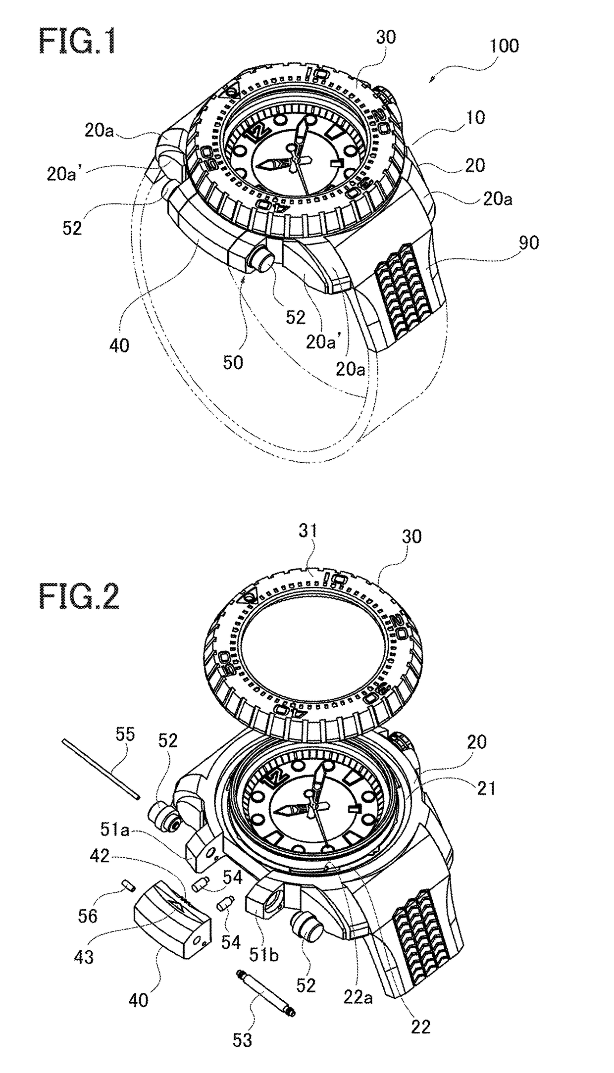
[0054]A wristwatch 100 (hereinafter, timepiece 100) shown in FIG. 1 is a diver's watch according to an embodiment of a timepiece according to the present invention. A band 90 is provided in a body 10 of the timepiece 100 in a direction connecting 12 o'clock and 6 o'clock on a clock face. A user put his or her arm into the band in a direction connecting 9 o'clock and 3 o'clock on the clock face.

[0055]A case (case member) 20 of the body 10 contains a timepiece movement and is equipped with, on a top face, a bezel 30 rotatable counterclockwise by a user's manipulation with his / her fingers. The case 20 may or may not include a not-shown rear cover.

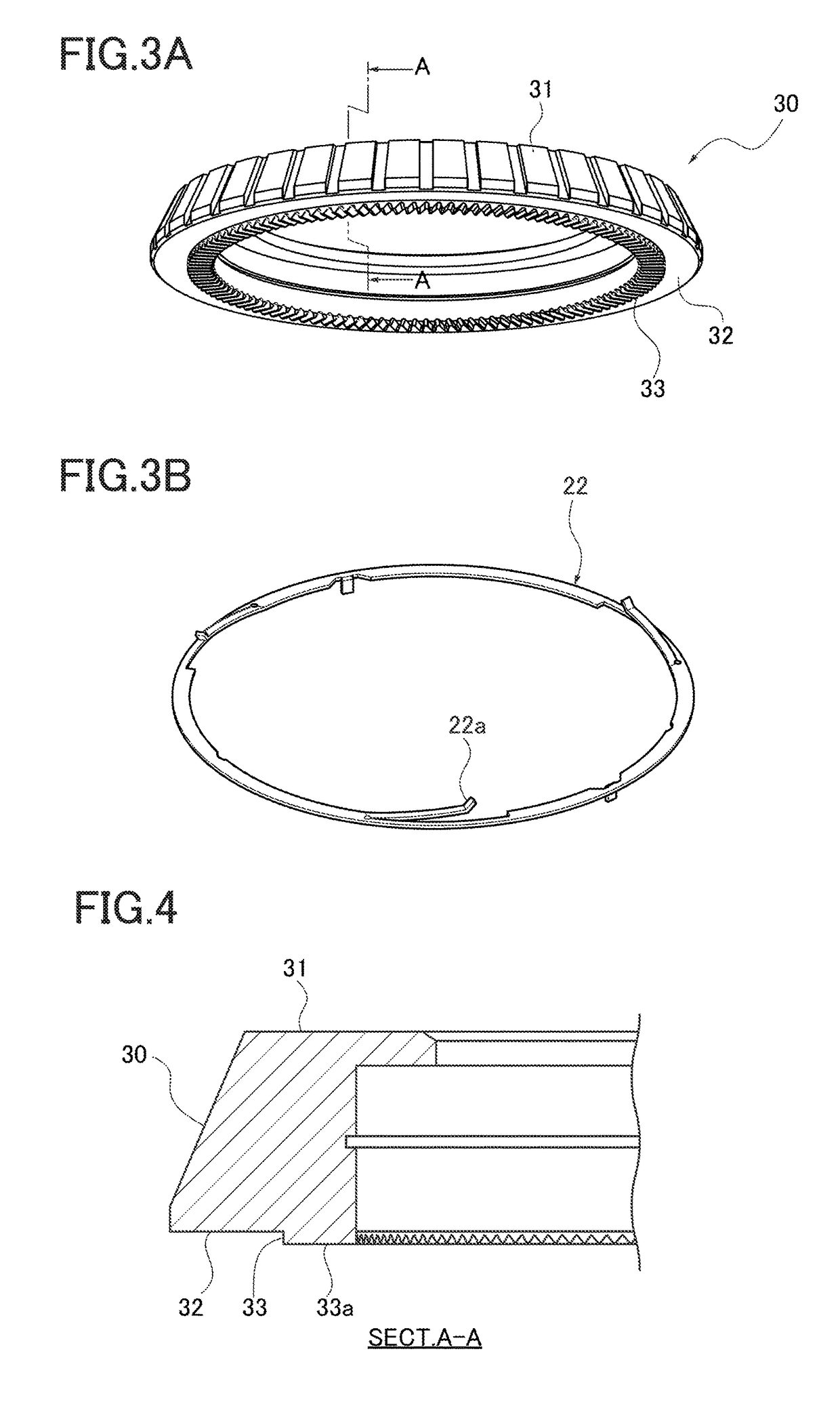
[0056]As shown in FIG. 2, numerals and scales are provided on a top face 31 of the bezel 30 to show remaining time and the like depending on a positional relationship with a minute hand of the body 10.

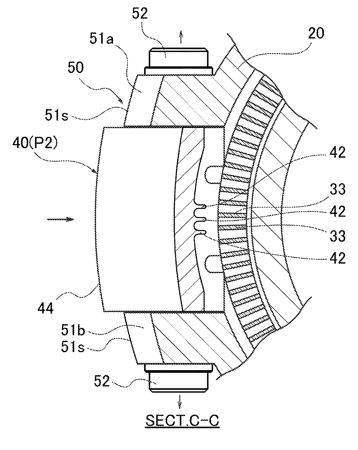
[0057]Meanwhile, teeth 33 ...


PUM


Abstract

Facilitate operations to release a bezel from a rotation prevented state and to rotate the bezel and avoid erroneously releasing the rotation prevented state. A timepiece includes a restrictor having engaging teeth and being movable between a restricted position and a release position by engaging / disengaging the engaging teeth with teeth of the bezel. The timepiece also has a holding mechanism holding the restrictor between a held state, i.e., restricted position and a non-held state. i.e., the release position. The holding mechanism includes two push-buttons and a release mechanism including a spring bar and engaging hole. The release mechanism switches the restrictor to the non-held state irrespective of a continuance of applying the pressing operation forces after the pressing operation forces are applied simultaneously to the two push-buttons.

Description

CROSS-REFERENCE TO RELATED APPLICATION[0001]The present application is based on and claims priority to Japanese patent application No. 2013-129610, filed on Jun. 20, 2013, the disclosure of which is hereby incorporated by reference herein in its entirety.[0002]The present invention relates to a timepiece, in particular, to improvement in a rotatable bezel.BACKGROUND ART[0003]A rotatable bezel is provided in the case of a so-called diver's watch, aiming for allowing users to easily know how much time is left for diving or other purposes. The bezel is rotatable to a certain position and then maintains the position. However, the bezel may be easily moved from the position when hit by an obstacle, for example.[0004]To prevent such an unintentional motion of the bezel, a rotation preventing (lock) mechanism has been proposed for allowing the bezel to rotate by rotational operation and restricting the rotation of the bezel in non-rotational operation (see Japanese Laid-Open Patent Applica...

Claims


Application Information

Patent Timeline
Patent Type & Authority Patents(United States)
IPC IPC(8): G04B19/18G04B19/22G04B19/28
CPCG04B19/286G04B19/18G04B19/22G04B19/223G04B19/225
Inventor KOBAYASHI, MICHIYUKI
Owner CITIZEN WATCH CO LTD
Why Eureka
Try Eureka