
Parking brake reset mechanism for railway vehicles

a technology for resetting the parking brake system and railway vehicles, which is applied in the direction of brake systems, brake components, transportation and packaging, etc., can solve the problems of increasing the amount of increasing the time needed to reset the parking brake system, and requiring extra equipment. to achieve the effect of fast reset tim

Active Publication Date: 2017-09-05
WABTEC HLDG CORP
View PDF4 Cites 2 Cited by
  • Summary
  • Abstract
  • Description
  • Claims
  • Application Information

AI Technical Summary

Benefits of technology

The patent text is about a parking brake reset system that can be reset quickly and without needing additional equipment. This system allows for a faster and more efficient recovery of the vehicle's ability to stop and move.

Problems solved by technology

Manually releasing the parking brakes allows the transit vehicle to roll freely for the move to, for example, a repair station but, once arriving at the desired destination, the parking brakes are no longer available to prevent motion of the transit vehicle once parked.
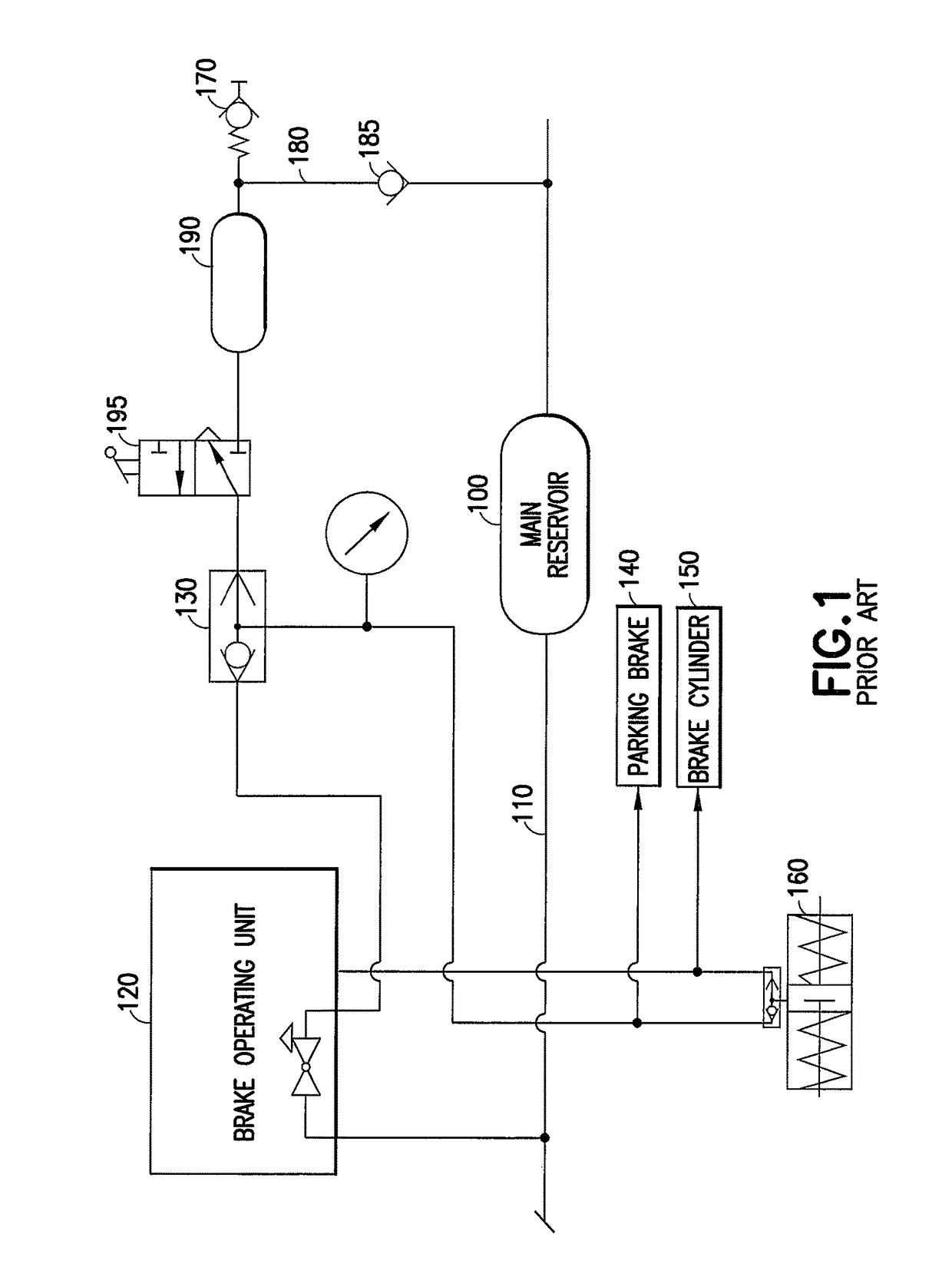
However, during a failure situation where the railway vehicle system loses pressurized air and the parking brake 140 has been manually released, the parking brake system must be reset before the parking brake can be applied on the disabled railway vehicle.
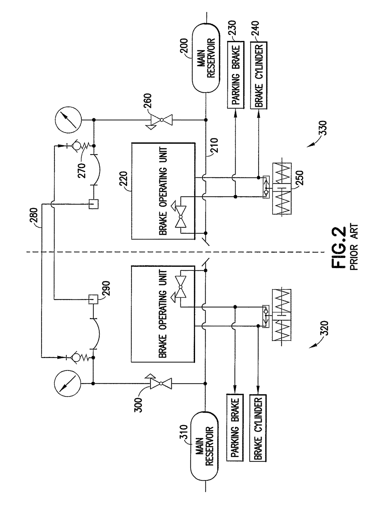
This involves resetting the parking brakes of each individual transit vehicle, which can increase the amount of time needed to reset the parking brake systems.
This method of resetting the parking brake systems for transit vehicles involves extra equipment and increased periods of time to reset the parking brake systems.

Method used


Image

  • Parking brake reset mechanism for railway vehicles
  • Parking brake reset mechanism for railway vehicles
  • Parking brake reset mechanism for railway vehicles

Examples


Embodiment Construction

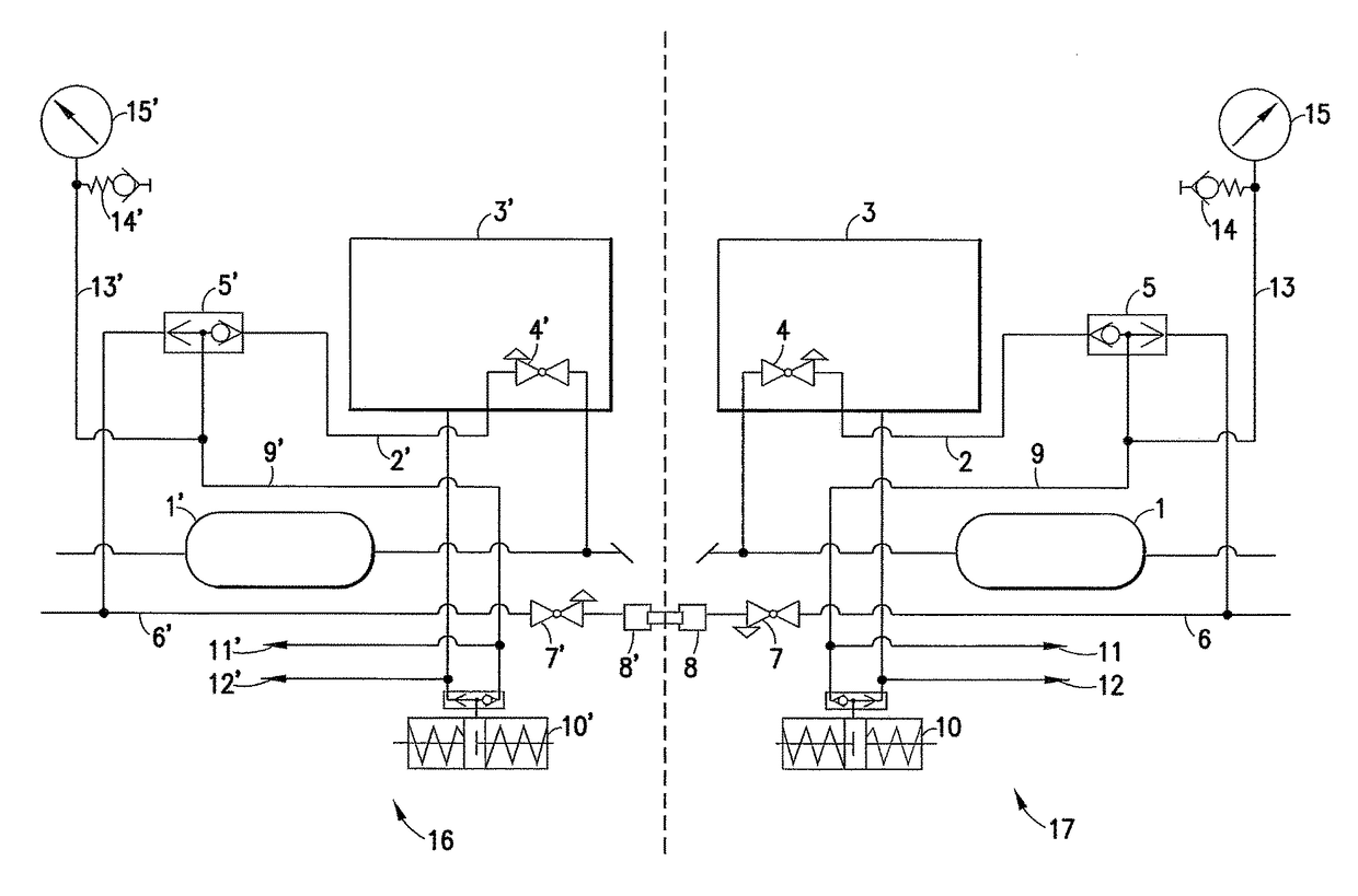
[0019]For purposes of the description hereinafter, spatial orientation terms, as used, shall relate to the referenced embodiment as it is oriented in the accompanying drawings, figures, or otherwise described in the following detailed description. However, it is to be understood that the embodiments described hereinafter may assume many alternative variations and configurations. It is also to be understood that the specific components, devices, features, and operational sequences illustrated in the accompanying drawing, figures, or otherwise described herein are simply exemplary and should not be considered as limiting. In the following description, like parts are designated with like numerals with a prime associated with the numerals designating an opposing railway vehicle.

[0020]Referring to FIG. 3, a parking brake reset system for a railway vehicle, such as a transit vehicle, is described herein. A main air reservoir 1 is fluidly connected to a control valve 5 via a reservoir dist...


PUM


Abstract

A parking brake reset system for a railway vehicle, such as a transit vehicle, includes a brake operating unit fluidly connected to a main air reservoir and controlling air flow to a brake cylinder of the railway vehicle, a brake pipe, a parking brake, and a control valve in line between the brake pipe and the parking brake to establish fluid communication between the brake pipe and the parking brake. The control valve is in line between the brake operating unit and the parking brake, whereby the control valve controls air flow to the parking brake from the main air reservoir and the brake pipe. The control valve may be a double check valve or a 3-way cutout valve, as examples.

Description

BACKGROUND OF THE INVENTION[0001]Field of the Invention[0002]This disclosure relates generally to a parking brake reset system for a railway vehicle, and more particularly, to a parking brake reset mechanism for a transit vehicle.[0003]Description of Related Art[0004]Currently known parking brake systems utilized in many transit vehicles are equipped with spring-applied air release parking brakes. This provides automatic application of the parking brakes whenever the parking brake system air pressure is lost. However, when transit vehicles are equipped with this type of parking brake system, the parking brakes must be manually released in order to move a disabled transit vehicle to a new location for repair. Manually releasing the parking brakes allows the transit vehicle to roll freely for the move to, for example, a repair station but, once arriving at the desired destination, the parking brakes are no longer available to prevent motion of the transit vehicle once parked.[0005]In ...

Claims


Application Information

Patent Timeline
Patent Type & Authority Patents(United States)
IPC IPC(8): B60T13/68B60T17/22B61H13/00B60T13/26B60T13/66B60T15/60
CPCB60T15/60B60T13/266B60T13/665B60T17/228B61H13/005
Inventor DEWBERRY, JAMES THOMASSCHARPF, ROBERT NORMAN
Owner WABTEC HLDG CORP
Learn More