Manufacturing method for a magnetic material core-embedded resin multilayer board

a technology of magnetic material and multi-layer board, which is applied in the field of manufacturing method of magnetic material coreembedded resin multi-layer board, can solve the problems of industrial problems, high manufacturing cost, and high manufacturing cost, and achieve the effects of variations of magnetic characteristics, not increasing the manufacturing cost, and reducing or preventing deterioration

Active Publication Date: 2017-08-29
MURATA MFG CO LTD
View PDF8 Cites 1 Cited by
  • Summary
  • Abstract
  • Description
  • Claims
  • Application Information

AI Technical Summary

Benefits of technology

[0008]Therefore, preferred embodiments of the present invention provide a magnetic material core-embedded resin multilayer board and a manufacturing method therefore that are able significantly reduce or prevent deterioration and variations of magnetic characteristics caused due to occurrence of an unexpected and unintended structural defect, without increasing the number of steps; and an electronic device including a magnetic material core-embedded resin multilayer board.
[0015]According to various preferred embodiments of the present invention, since the magnetic material core is fractured along the conductor pattern, that is, an unexpected and unintended structural defect has not occurred therein, a step of attaching a large number of magnetic materials in the form of small pieces to a resin sheet is unnecessary, and the manufacturing cost is not increased. In addition, it is possible to provide a stable magnetic material core-embedded resin multilayer board that is able significantly reduce or prevent deterioration and variations of magnetic characteristics of the magnetic material core, and it is possible to provide an electronic device including the magnetic material core-embedded resin multilayer board.

Problems solved by technology

However, a crack, a chip, a fracture, or the like is likely to occur in the magnetic material core in a pressure-bonding step during manufacture of the resin multilayer board.
However, in order to embed the magnetic material in the form of small pieces in the resin multilayer board, a step of attaching a large number of magnetic materials, in the form of small pieces, to a resin sheet is necessary, which is industrially problematic.

Method used


Image

  • Manufacturing method for a magnetic material core-embedded resin multilayer board
  • Manufacturing method for a magnetic material core-embedded resin multilayer board
  • Manufacturing method for a magnetic material core-embedded resin multilayer board

Examples


first preferred embodiment

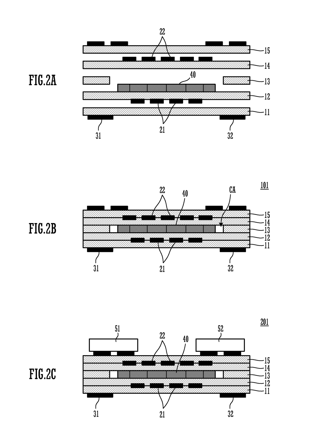
[0027]FIG. 1 is an exploded perspective view of an antenna device 101 according to a first preferred embodiment of a magnetic material core-embedded resin multilayer board of the present invention, FIG. 2A is a cross-sectional view of the antenna device 101 before stacking, FIG. 2B is a cross-sectional view of the antenna device 101, and FIG. 2C is a cross-sectional view of an antenna module 201 configured by mounting chip components on the antenna device 101. It should be noted that in FIGS. 1 and 2A to 2C, principal components related to various preferred embodiments of the present invention are shown, and illustration of the other components are partially omitted.

[0028]The antenna device 101 includes a resin multilayer board in which a plurality of resin sheets 11, 12, 13, 14, and 15 are stacked; and a coil conductor provided in the resin multilayer board. A plurality of line portions 21 of the coil conductor are provided on a lower surface of the resin sheet 12, and line portion...

second preferred embodiment

[0036]FIGS. 4, 5A, and 5B are diagrams showing the structure of a portion of an antenna device according to a second preferred embodiment of the present invention and a non-limiting example of a manufacturing method therefor. FIG. 4 is a perspective view of the magnetic material core 40, FIG. 5A is a cross-sectional view of the resin sheet 12 and the magnetic material core 40, and FIG. 5B is a cross-sectional view in a state where the magnetic material core 40 is stacked on the resin sheet 12.

[0037]The manufacturing method for the antenna device of the second preferred embodiment includes a “crack positioning step” for predetermining positions at which cracks are to be formed in the magnetic material core. The magnetic material core 40 shown in FIGS. 4 and 5A includes a plurality of grooves GR. In a later step, cracks are formed (fractures occur) at the positions of the grooves GR. The grooves GR are formed preferably by forming grooves on an unsintered green sheet for the magnetic ...

third preferred embodiment

[0040]FIG. 6 is a cross-sectional view of a principal portion of an antenna device according to a third preferred embodiment of the present invention. It should be noted that in this example, the antenna device is not merely an antenna device but is an antenna device configured with the antenna module 201 (i.e., including an antenna module). The antenna device includes the antenna module 201 and a booster coil 301. The configuration of the antenna module 201 is as described in the first preferred embodiment, and an antenna portion 101P within the antenna module 201 is preferably used as a feeding coil configured to couple with the booster coil 301.

[0041]FIG. 7 is an exploded perspective view of the booster coil 301. The booster coil 301 includes an insulator substrate 3, a first coil 1 provided on a first surface of the insulator substrate 3, a second coil 2 provided on a second surface of the insulator substrate 3, and a magnetic material sheet 4. Each of the first coil 1 and the s...


PUM

PropertyMeasurementUnit
thicknessaaaaaaaaaa
magnetic characteristicsaaaaaaaaaa
magneticaaaaaaaaaa

Abstract

An antenna device includes a resin multilayer board in which a plurality of resin sheets are stacked, and a coil conductor provided in the resin multilayer board. A plurality of line portions of the coil conductor are provided on a lower surface of the resin sheet. When a magnetic material core is preliminarily pressure-bonded to the resin sheet, the magnetic material core is fractured along the line portions and cracks occur. Thus, the resin sheet with the magnetic material core in which the cracks have been formed is fully pressure-bonded together with the other resin sheets.

Description

BACKGROUND OF THE INVENTION[0001]1. Field of the Invention[0002]The present invention relates to a resin multilayer board including a magnetic material core embedded therein, a manufacturing method therefor, and an electronic device including a magnetic material core-embedded resin multilayer board.[0003]2. Description of the Related Art[0004]Japanese Patent No. 4218635 discloses an antenna device that includes a magnetic material and is used in an RFID system that performs data communication in a non-contact manner.[0005]FIG. 10 is a cross-sectional view of an antenna-integrated magnetic sheet disclosed in Japanese Patent No. 4218635. In FIG. 10, an antenna-integrated magnetic sheet 81 includes, in a sheet substrate 84, an antenna pattern 82 and magnetic material solid pieces 90 that are sintered bodies. In Japanese Patent No. 4218635, since the magnetic material is placed within the sheet substrate in a state of being formed into small pieces, deterioration of characteristics caus...

Claims


Application Information

Patent Timeline
Patent Type & Authority Patents(United States)
IPC IPC(8): H01P11/00H01Q13/00H01Q1/24G06K19/077H05K1/16H05K3/44H01Q7/06H05K1/02H05K3/46
CPCH01Q7/06G06K19/07722G06K19/07779H01Q1/243H05K1/165H05K3/44G06K19/07794H05K1/0239H05K3/4602H05K3/4617H05K2201/086H05K2201/10098H05K2203/0278H05K2203/063H05K2203/1131Y10T29/49016
Inventor YOSUI, KUNIAKIGOUCHI, NAOKI
Owner MURATA MFG CO LTD
Why Eureka
Try Eureka