
Ceiling system

a ceiling and floor technology, applied in the field of ceiling systems, to achieve the effect of not altering or affecting the overall visual appearan

Active Publication Date: 2017-08-29
AWI LICENSING
View PDF38 Cites 9 Cited by
  • Summary
  • Abstract
  • Description
  • Claims
  • Application Information

AI Technical Summary

Benefits of technology

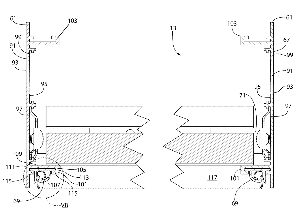
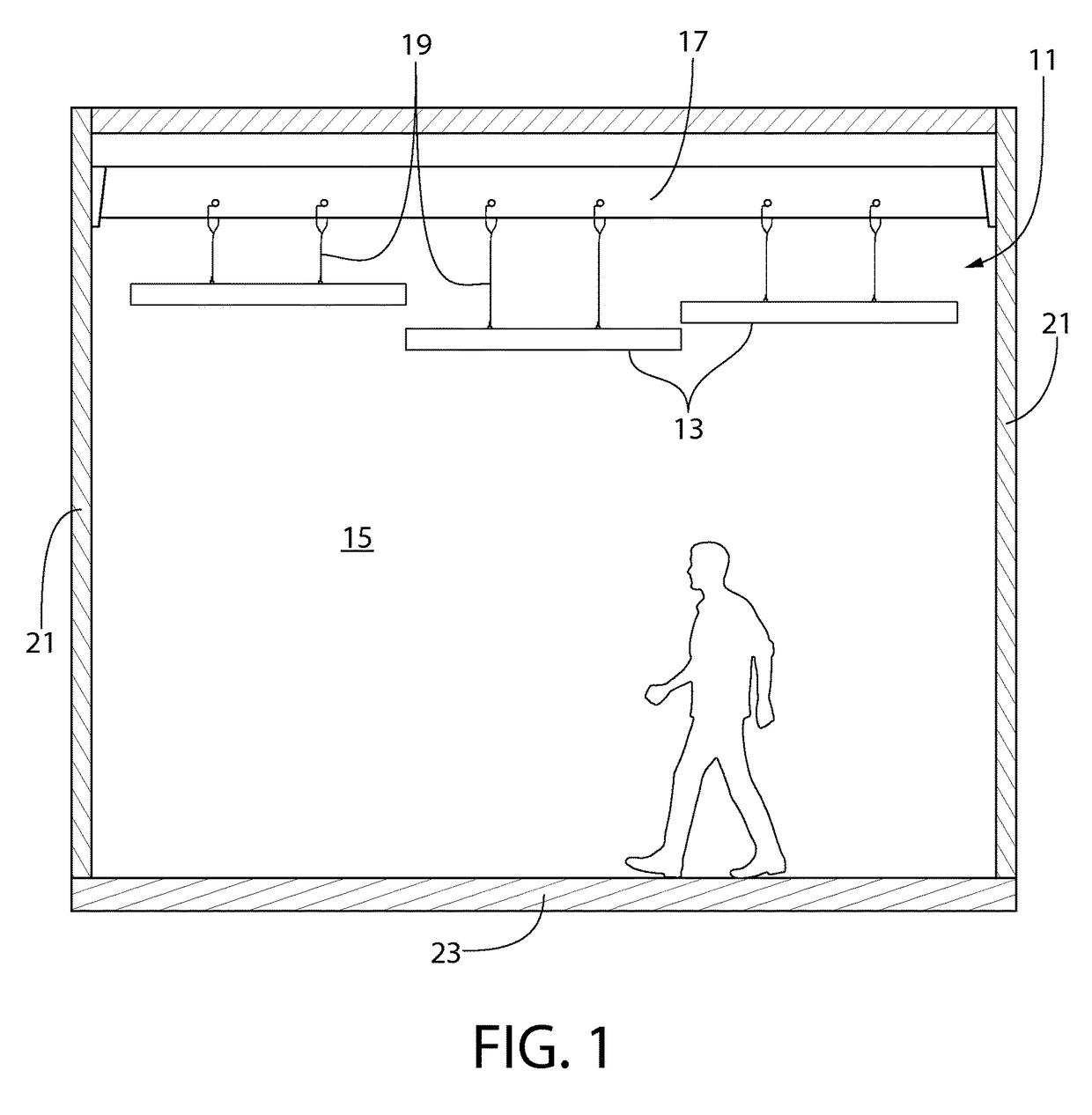
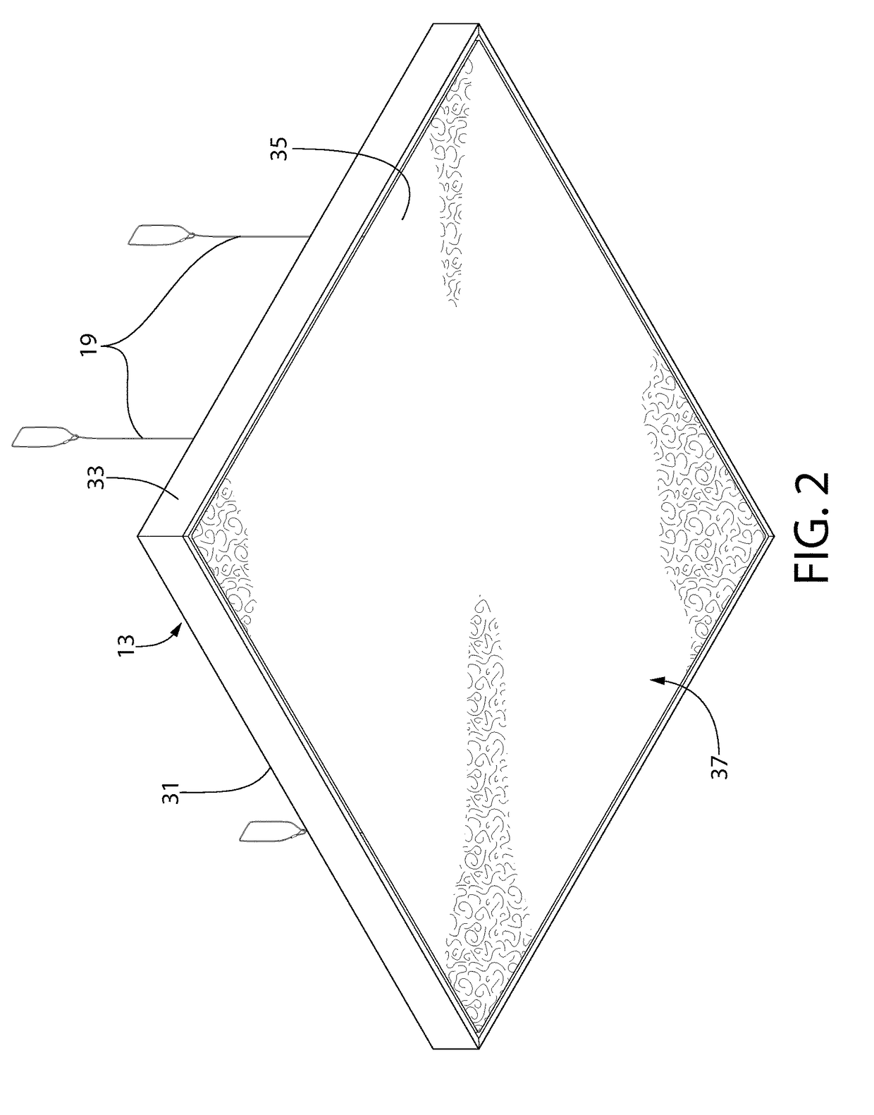
The present invention is a ceiling system that offers a seamless visual appearance and allows for fine tuning of acoustic properties without affecting the overall visual appearance. The ceiling structure is suspended from an overhead structure and includes a frame and a grid of acoustic ceiling panels. The fabric is stretched across the entire ceiling structure to create a seamless appearance. This design creates an impression that the ceiling is one continuous piece, rather than a collection of separate parts.

Problems solved by technology

One of the biggest challenges for acoustic ceilings is the balance between acoustic performance and visual appearance.
However, it is inescapable that a grid of acoustic ceiling panels, even with a hidden grid system, can still appear as a grid of acoustic ceiling panels.

Method used


Image

  • Ceiling system
  • Ceiling system
  • Ceiling system

Examples


Embodiment Construction

[0026]The following description of the preferred embodiment(s) is merely exemplary in nature and is in no way intended to limit the invention, its application, or uses.

[0027]As used throughout, ranges are used as shorthand for describing each and every value that is within the range. Any value within the range can be selected as the terminus of the range. In addition, all references cited herein are hereby incorporated by referenced in their entireties. In the event of a conflict in a definition in the present disclosure and that of a cited reference, the present disclosure controls.

[0028]In the description of embodiments disclosed herein, any reference to direction or orientation is merely intended for convenience of description and is not intended in any way to limit the scope of the present invention. Relative terms such as “lower,”“upper,”“horizontal,”“vertical,”, “above,”“below,”“up,”“down,”“top” and “bottom” as well as derivative thereof (e.g., “horizontally,”“downwardly,”“upw...


PUM


Abstract

A ceiling system including: a ceiling structure suspended in an interior space. The ceiling structure includes: a perimeter frame defining a central opening, the perimeter frame comprising a fabric gripping member; a support grid comprising a plurality of intersecting struts defining a plurality of grid openings, the support grid disposed within the central opening and coupled to the perimeter frame; a plurality of acoustic ceiling panels, each of the acoustic ceiling panels mounted to the support grid and disposed in one of the grid openings; and a tensioned fabric sheet having a perimeter portion that is engaged by the fabric gripping member of the perimeter frame, the tensioned fabric sheet located below the acoustic ceiling panels and covering the central opening.

Description

BACKGROUND[0001]The present invention generally relates to ceiling systems, and more particularly to suspended ceiling systems which create a seamless appearance.[0002]One of the biggest challenges for acoustic ceilings is the balance between acoustic performance and visual appearance. On one extreme, acoustic ceilings which are integrally formed with the top surface of a space sacrifice significant acoustic performance in favor of a very uniform and seamless visual appearance. On the other extreme, acoustic ceilings formed of acoustic ceiling panels installed within a grid system are able to significantly increase the acoustic performance of the acoustic ceiling, but only at the sacrifice of a seamless visual appearance. Acoustic ceilings have therefore been introduced which hide the grid system, by concealing it within the edges of the supported acoustic ceiling panels, in order to present a more visually appealing appearance to the ceiling. However, it is inescapable that a grid ...

Claims


Application Information

Patent Timeline
Patent Type & Authority Patents(United States)
IPC IPC(8): E04B9/24E04B9/18E04B9/04E04B9/06
CPCE04B9/245E04B9/04E04B9/06E04B9/18E04B2009/0492E04B9/0428E04B9/122E04B9/363
Inventor BERGMAN, TODD M.
Owner AWI LICENSING
Learn More