Programmable logic device and logic integration tool
a logic integration and programmable logic technology, applied in logic circuits, logic functions, pulse techniques, etc., can solve the problems of inability to apply asic, the cost of designing and manufacturing masks for asic manufacturing, and the inability to design and manufacture asic masks, etc., to achieve high error resistance and high reliability/high safety programmable logic
- Summary
- Abstract
- Description
- Claims
- Application Information
AI Technical Summary
Benefits of technology
Problems solved by technology
Method used
Image

Examples
first embodiment
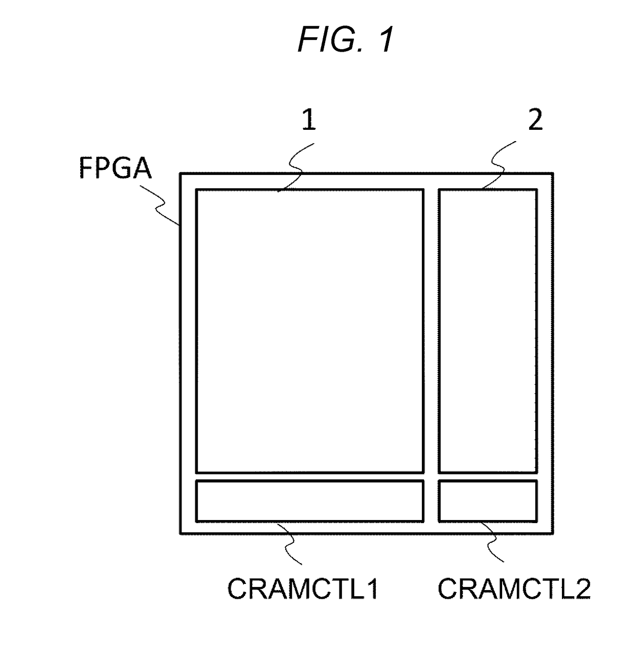
[0030]An FPGA according to this embodiment is illustrated in FIG. 1. The FPGA is configured by integrating a plurality of logic elements into a tile shape. In addition, the FPGA is divided into at least two areas. In addition, one of the two areas corresponds to the high reliable area and becomes a high reliable mounting part 2 to be a portion where high reliability is secured with respect to a soft error. The other corresponds to the other area and becomes a large-capacity logic mounting part 1 to be a portion where operation logic to realize functions of a device is integrated. The large-capacity logic mounting part 1 becomes a portion where reliability is low as compared with the high reliable mounting part 2. However, in this embodiment, importance is placed on that logic is mounted at high density.
[0031]In this embodiment, in the high reliable area, the check frequency of the CRAM is set higher than the check frequency of the other area. Specifically, in this embodiment, checks...
second embodiment
[0046]An FPGA according to this embodiment is illustrated in FIG. 6. Even in this embodiment, a large-capacity logic mounting part 1 and a high reliable mounting part 2 are provided. The high reliable mounting part 2 uses a CRAM having a relatively large transistor size, is configured such that a thickness of a gate insulating film of a MISFET to be formed is large, and endures application of a high voltage. As a result, a high power supply voltage is set to the CRAM of the high reliable mounting part 2 as compared with a CRAM of the other area. As compared with the first embodiment, a signal level conversion circuit LS is added.
[0047]According to this embodiment, because the CRAM of the high reliable mounting part 2 can be designed to have a large holding charge amount as compared with a CRAM of the large-capacity logic mounting part 1, the CRAM can have high resistance to charge accumulation by the entry of charged particles caused when radiations such as neutrons collide other at...
third embodiment
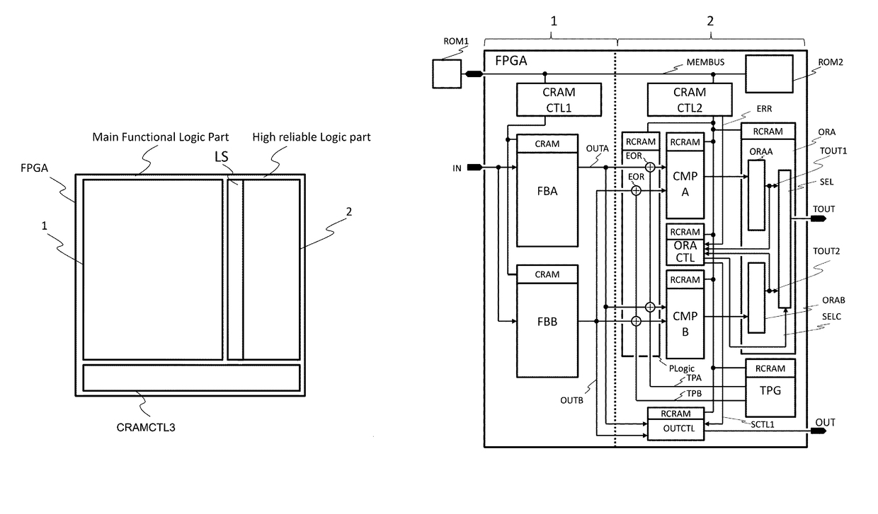
[0058]An example of integration of a large-capacity logic mounting part 1 and a high reliable mounting part 2 of an FPGA according to this embodiment is illustrated in FIG. 9. In this embodiment, a plurality of comparators are multiplexed and provided. Specifically, the large-capacity logic mounting part 1 and the high reliable mounting part 2 are provided in the FPGA and functions are realized by a functional block FBA and a functional block FBB duplicated in the large-capacity logic mounting part 1. A CRAM to store logic information and wiring line switching information is defined in each of the functional blocks FBA and FBB. This drawing illustrates a physical relation such that the corresponding CRAMs become clear according to the functions, not a physical arrangement. In the CRAM, writing of data from a ROM and checking of storage information of the CRAM are executed by a CRAM control part 1CRAMCTL1. The high reliable mounting part 2 includes comparators CMPA and CMPB comparing...
PUM
 Abstract
Description
Claims
Application Information
 - R&D
- Intellectual Property
- Life Sciences
- Materials
- Tech Scout
- Unparalleled Data Quality
- Higher Quality Content
- 60% Fewer Hallucinations
Browse by: Latest US Patents, China's latest patents, Technical Efficacy Thesaurus, Application Domain, Technology Topic, Popular Technical Reports.
© 2025 PatSnap. All rights reserved.Legal|Privacy policy|Modern Slavery Act Transparency Statement|Sitemap|About US| Contact US: help@patsnap.com