
Continuum style manipulator actuated with phase change media

a technology of phase change and manipulator, which is applied in the direction of arms, manufacturing tools, applications, etc., can solve the problems of complex, fragile, expensive, and expensive of conventional robotic manipulators, and can not be both passively conforming to their environments and maintaining complex, arbitrary configurations., and achieves high-articulation effects

Active Publication Date: 2017-07-25
MASSACHUSETTS INST OF TECH
View PDF28 Cites 10 Cited by
  • Summary
  • Abstract
  • Description
  • Claims
  • Application Information

AI Technical Summary

Benefits of technology

[0027]A class of manipulator is disclosed herein that is robust, high-force, low-cost, and highly articulated, without employing traditional actuators mounted at the manipulator joints. Rather, local tunable stiffness is coupled with off-board spooler motors and tension cables to achieve complex manipulator configurations. Tunable stiffness is achieved by reversible jamming and unjamming of granular media, which—by applying a vacuum to enclosed grains—causes the grains to transition between solid-like states when jammed and liquid-like ones when not-jammed. Other phase change media may also be used rather than jammable media.
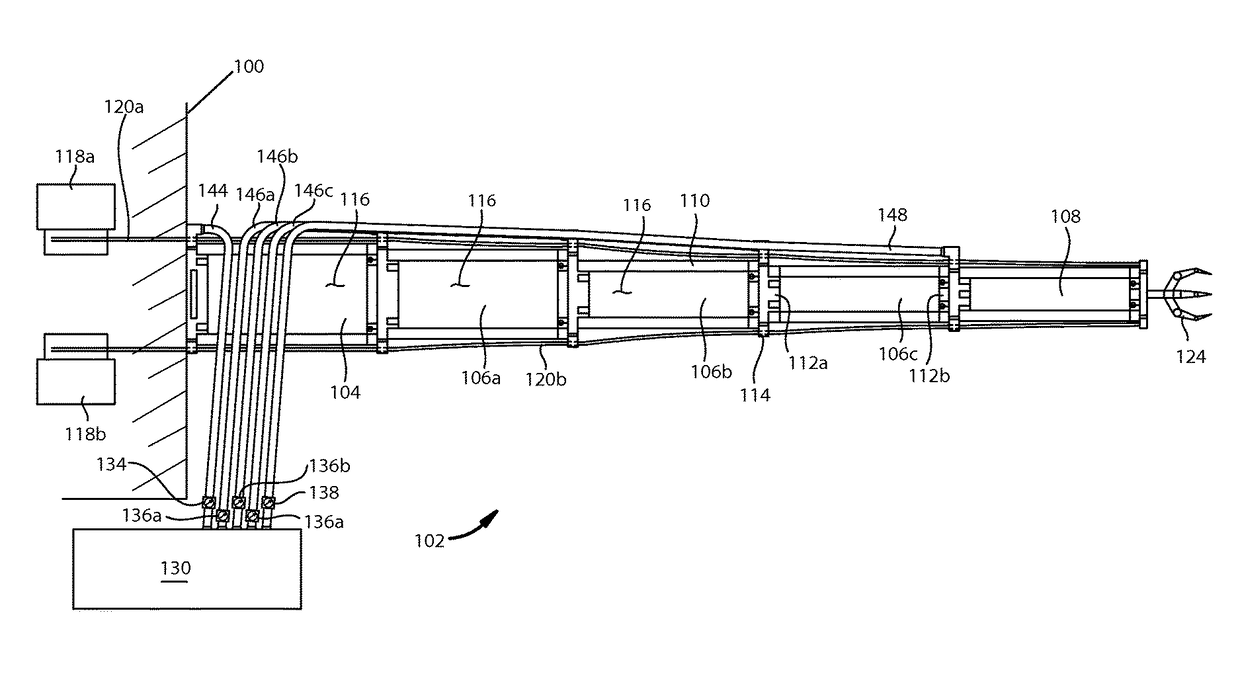
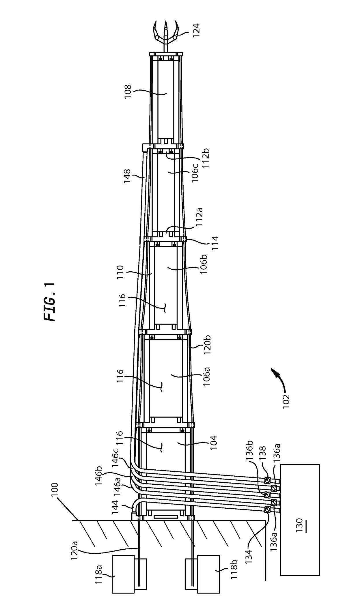
[0030]This novel design for a manipulator, and use of jamming for robotic applications in general can greatly benefit many applications, such as human-safe robotics and systems in which robots need to exhibit high flexibility to conform to their environments. The control of the conformation of the manipulator can be robust and elegant. For instance, as shown with reference to FIGS. 4 and 3F, the manipulator can wrap around an object using binary local control (i.e. controlling individual modules to assume one of two states: jammed or not-jammed) and off-board control of the tension cables. The not-jammed modules can passively conform to other objects. The disclosed manipulator is able to fold back on itself, as shown schematically in FIG. 3C and maintain highly articulated configurations via jamming. The reachable workspace boundary of the manipulator is nearly a sphere with a radius equal to the manipulator length.

Problems solved by technology

Conventional robotic manipulators can be fragile, expensive, and limited in their flexibility, due to the distributed rigid and bulky actuators that are typically used to achieve the precision and degrees of freedom (DOFs) required.
While these traditional snake robots have impressive capabilities and are useful in many applications such as search-and-rescue, they can be complex, fragile, and expensive.
Such systems are not typically capable of both passively conforming to their environments and maintaining complex, arbitrary configurations.
Cable-driven systems can be controlled by traditional actuators, such as motors, and are also highly dexterous.
These manipulator-type systems are often found in (but not limited to) surgical devices, which typically are too small to include on-board actuators.
Many of them lack the ability to lock arbitrary segments in place, thus complicating the control of the robot.
In many cases, these environments are harsh, either in terms of temperature, chemical content (such as in a gas chamber, or within a liquid environment).
Thus, it is sometimes a challenge to provide an actuator that can withstand the environment.
Thus, in environments where the manipulator operates near or interacts with living humans (or animals), there is a risk of injury to the humans or animals, in the case of inadvertent forceful or high-momentum contact of the robot with the human.
Further, assembly line robots that swing, extend, turn and grip might injure an operator if contact were to be made.
Thus expensive and inconvenient enclosures must be provided around such robots.
To do this with conventional manipulators requires a complicated control scheme.
Conventional robots often have a limited workspace, due to their rigidity.
For instance, they may be able to access locations around the surface of a sphere, but are not able to access locations that are radially inward of the outermost spherical surface.

Method used


Image

  • Continuum style manipulator actuated with phase change media
  • Continuum style manipulator actuated with phase change media
  • Continuum style manipulator actuated with phase change media

Examples


Embodiment Construction

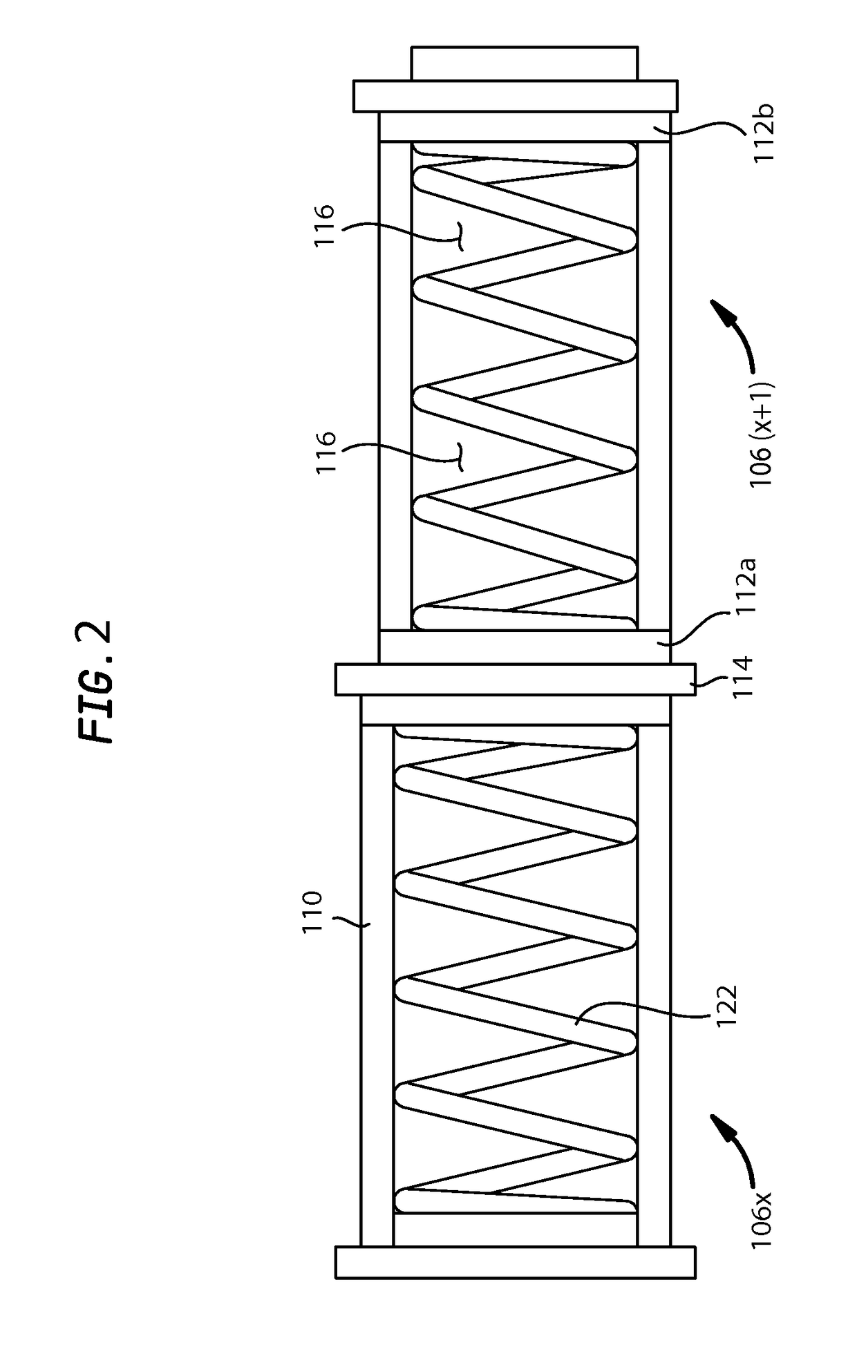
[0034]FIG. 1 illustrates schematically in cross-section, a representative implementation of a jammable manipulator 102. The manipulator is coupled to ground 100 (shown as a wall) through a base module 104. Intermediate modules 106a, 106b and 106c couple the base module 104 to a terminal module 108. As shown more clearly in FIG. 2, each module is composed, in part, of an envelope 110, which is coupled to a basal end cap 112a and a terminal end cap 112b, arranged toward the base module 104 and the terminal module 108, respectively. Each envelope is fluidically isolatable from the ambient environment, so that a relatively lower pressure, such as a vacuum, or close to a vacuum, when air is the fluid, as compared to atmospheric pressure, can be maintained within each module. The fluid can be air, water, or any other suitable working fluid. Typically, it is air, and the examples shown herein use air as the working fluid.

[0035]It is also possible, as explained below, to establish a pressur...


PUM


Abstract

A continuum style manipulator is actuated by jammable media within an envelope of a module, which is also actuated by a tensile element, such as a cable and spooler motor. Multiple modules may be reversibly added. Two or more tensile elements may also be used. Three or more actuated tensile elements can actuate three DOFs of each module, and the terminal module, as well as the entire manipulator. Jammable media may be granular, actuated by a pressure change. Coarsely ground coffee works well. Rather than a jammable media, tensile elements may alternatively be used with other phase change media, such as magnetorheological and electrorheological media. A high friction angle of the granular media is desirable, and has been achieved with a particle size dispersion including both small and relatively larger particles. Applications include endoscopes, proctoscopes, laparoscopic instruments, manufacturing and medical manipulators. Methods of actuating include unjamming all modules, positioning the manipulator with tensile elements or otherwise, jamming the base-most module, and then repositioning remaining, not-jammed modules, followed by jamming the base-most not-jammed module, and so on, until all modules are positioned and jammed.

Description

RELATED DOCUMENTS[0001]This is the 35 U.S.C. §371 U.S. National Phase of Patent Cooperation Treaty application No. PCT / US2013 / 030354, entitled, CONTINUUM STYLE MANIPULATOR ACTUATED WITH PHASE CHANGE MEDIA, International filing date of 12 Mar. 2013, to which the benefit of priority is hereby claimed. The PCT application claims the benefit of U.S. Provisional application No. 61 / 646,280 filed on May 12, 2012, entitled CONTINUUM STYLE MANIPULATOR ACTUATED WITH PHASE CHANGE MEDIA AND TENSILE ELEMENTS. The entire disclosure of each application mentioned above is hereby incorporated fully herein, by reference.GOVERNMENT RIGHTS[0002]This invention was made with government support under Grant No. W911NF-11-C-0201 awarded by the Army Research Office. The government has certain rights in this invention.INTRODUCTION[0003]Conventional robotic manipulators can be fragile, expensive, and limited in their flexibility, due to the distributed rigid and bulky actuators that are typically used to achie...

Claims


Application Information

Patent Timeline
Patent Type & Authority Patents(United States)
IPC IPC(8): B65G1/00B25J18/06A61B1/00A61B1/005B25J9/10A61B34/00
CPCB25J18/06A61B1/0016A61B1/0057A61B1/00078A61B1/00147A61B34/70A61B34/71B25J9/1085A61B2034/715Y10T74/20323A61B2017/00566A61B1/00148
Inventor CHENG, NADIA G.LABOVSKY, MAXIM B.HOSOI, ANNETTE E.IAGNEMMA, KARL D.
Owner MASSACHUSETTS INST OF TECH
Learn More