
Portable calisthenics exercise device

a calisthenics and exercise device technology, applied in the field of physical exercise equipment, can solve the problems of difficult access, difficulty in moving back and forth from the wheelchair to the floor, etc., and achieve the effects of increasing the flexibility of muscle tissues, increasing the body movement, and facilitating movemen

Active Publication Date: 2017-07-25
ROGERS KIM
View PDF27 Cites 15 Cited by
  • Summary
  • Abstract
  • Description
  • Claims
  • Application Information

AI Technical Summary

Benefits of technology

[0011]Disclosed is a portable device designed for performing different callisthenic exercises, such as stretching, bending, twisting, pushups, leg lifts, dips, etc. The device allows the exerciser to increase his body movement without using a back support or a neck support, such as a padded board, or when lying on the floor. The device challenges strength training to all extremes using only muscle movement and flexibility of every exercise being performed for every person, along with the development for increasing flexibility of muscle tissues by the stretching movements for the muscle groups being used during the persons exercise fitness training being performed.
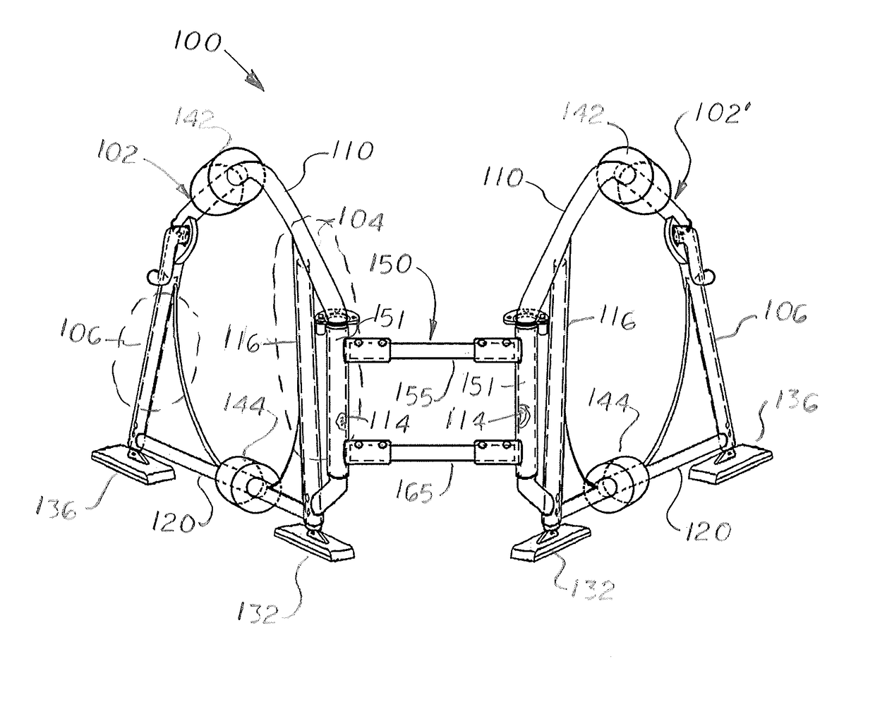
[0012]The device includes a right frame support and a left frame support linked by an intermediately located fork assembly. The right and left frame supports are slight angled inward so they converge to provide greater stability and support when used. The front sections of the two frame supports are pivotally connected to the fork assembly. In one embodiment, the fork assembly includes a length adjustable upper connector bar and a length adjustable lower connector bar that allows the spacing between the two front sections to be adjusted.
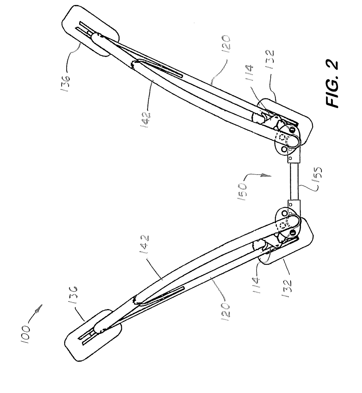
[0013]Each frame support includes an upper support bar and a lower support bar. In one embodiment, the upper support bar is curved upward over a straight lower support bar. Each frame support includes a front bar that is pivotally connected to the front fork. The rear sections of the two frame supports are detached from each other thereby allowing them to be selectively spaced apart and form a V-shaped exercise space between the two frame supports. When exercising, the exerciser adjusts the angles of the two frame supports so they may support the exerciser's hands, arms, legs, and feet at a desired position required for the exercise. Sometimes, the frame supports are moved to allow a wheelchair to be positioned in the V-shaped space. When exercising, the exerciser positions himself partially or entirely inside the V-shaped exercise space and uses the two frame supports to support his hands, arms, legs, and the upper and lower torsos. By moving the two rear sections inward or outward, the exerciser can adjust size and shape of the V-shaped exercise space.
[0016]When performing a callisthenic exercise, the exerciser may stand upright or lay in a supine or prone position. The exerciser may use the suspension seat and positioned himself in a sitting position between the two frame supports. The exerciser may grip the upper curved bars, the lower curved bars, the set of first handles, the set of second handles. When one or both horizontal bars are used, the exerciser may use them as support structures for bending around. After performing a callisthenic exercise, the exerciser can easily adjust the spacing of the front fork assembly, the lengths of the front and rear legs, and the angles of the handles, and remove the suspension seat or horizontal bars to perform the next desired exercise.

Problems solved by technology

These individuals find it difficult to move back and forth from the wheelchair to the floor.
Also, because elevated exercise bars and weight benches are usually fixed objects that are difficult to access when sitting in a wheelchair.

Method used


Image

  • Portable calisthenics exercise device
  • Portable calisthenics exercise device
  • Portable calisthenics exercise device

Examples


Embodiment Construction

)

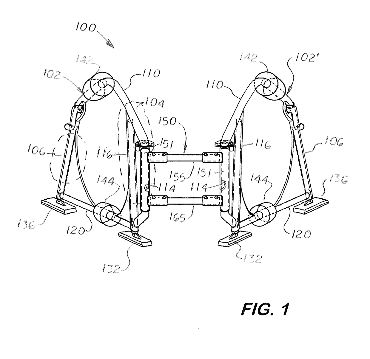
[0063]Referring to the accompanying FIGS. 1-12, there is shown a portable device 100 designed for performing different callisthenic exercises, such as stretching, bending, twisting, push ups, leg lifts, dips, etc. More specifically, FIGS. 1-6 is a front perspective view of the portable physical exercise device 100 that includes a rigid, right frame support 102 and a rigid left frame support 102′ connected to an intermediate front fort assembly 150.

[0064]Each frame support 102, 102′ includes an upper support bar 110 and a lower support bar 120. The upper support bar 110 is U-shaped and configured to curve upward over the straight lower support bar 120. The upper support bar 110 includes a front tube 116 that connects to the front end of the lower support bar 120.

[0065]Extending forward from the upper support bar 110 and the lower support bar 120 is a front extension 111. Each front extension 111 includes upper and lower extension arm 112, 113, respectively, and a vertical arm 114 di...


PUM


Abstract

A device for supporting an exerciser performing callisthenic exercises that includes a right and left, rigid, upright frame supports and an intermediate fork assembly. The fork assembly is adjustable in length and linked to the front sections of the two frame supports. Each frame support is angled inward to provide greater stability. The rear sections of the frame supports are detached and may be rotated laterally to reposition the gripping surfaces on the two frame supports and to adjust the size of the exercise space located between the two frame supports to accommodate different individuals and exercises. Each frame support includes an adjustable front leg and an adjustable rear leg that allows height adjustment of each frame support. The device may include one or two pairs of handles attached to the two frame supports, and a suspension seat and one or two horizontal bars extending between the two frame supports.

Description

[0001]This utility patent application is based upon U.S. provisional patent application (Application No. 61 / 653,697) filed on May 31, 2012.[0002]Notice is given that the following patent document contains original material subject to copyright protection. The copyright owner has no objection to the facsimile or digital download reproduction of all or part of the patent document, but otherwise reserves all copyrights.BACKGROUND OF THE INVENTION[0003]1. Field of the Invention[0004]This invention relates to physical exercising equipment, and more particularly to physical exercising equipment used for performing different callisthenic exercises.[0005]2. Description of the Related Art[0006]Many individuals prefer doing calisthenics rather than running or walking or working out using a treadmill, an elliptical machine, or a stationary bicycle. Calisthenics are types of exercises comprising a variety of simple, often rhythmical, movements of specific body parts or movements of the entire b...

Claims


Application Information

Patent Timeline
Patent Type & Authority Patents(United States)
IPC IPC(8): A63B26/00A63B23/04A63B23/035A63B21/00A63B21/002A63B23/12A63B23/02A63B21/068A63B23/00
CPCA63B26/00A63B21/00047A63B21/068A63B21/4009A63B21/4013A63B21/4035A63B23/0211A63B23/0216A63B23/0238A63B23/0355A63B23/0494A63B23/1218A63B23/1227A63B23/1236A63B2023/0411A63B2208/0204A63B2208/028A63B2208/0223A63B2208/0233A63B2208/0247A63B2208/0252A63B2208/0257A63B2210/50A63B2225/09A63B2225/093A63B2023/006
Inventor ROGERS, KIM
Owner ROGERS KIM
Learn More