Display device

a display device and display screen technology, applied in the field of display devices, can solve the problems of difficult subjects to obtain a sense of realism, viewer does not feel, image but finds difficulty in empathizing, etc., and achieves the effect of a strong sense of realism and easy visual recognition of spatial images

Active Publication Date: 2017-07-11
NITTO DENKO CORP
View PDF13 Cites 3 Cited by
  • Summary
  • Abstract
  • Description
  • Claims
  • Application Information

AI Technical Summary

Benefits of technology

[0009]In view of the foregoing, it is therefore an object of the present invention to provide a display device capable of displaying a two-dimensional video picture corresponding to an information holding element disposed around an image-forming optical element and appearing three-dimensional over the device at an appropriate moment with a strong sense of realism.
[0015]Using the signal information (information inherent in the information holding element) provided from the reader that reads information in a non-contacting manner and the signal information (detection signal of the information holding element) provided from the sensor that senses whether an object is present on the upper surface of the enclosure or not, the display device according to the present invention quickly performs switching between the standby state in which the individual information in the information holding element in proximity to the upper surface of the enclosure is read and the video picture corresponding to the information holding element is prepared and the display state in which the prepared video picture is image-formed through the image-forming optical element in space over the enclosure. Thus, the display device according to the present invention is capable of displaying a two-dimensional video picture corresponding to the information holding element and appearing three-dimensional over the device at an appropriate moment in a manner floating up. Therefore, the display device according to the present invention is capable of displaying an effective spatial image corresponding to the information holding element at an optimum moment with a strong sense of realism as if the spatial image existed there.
[0016]In the display device according to the present invention wherein the information holding element is planar and includes a light-transmissive part provided in a portion thereof and corresponding to the two-dimensional shape of the image-forming optical element, the projected image is image-formed through the light-transmissive part. Because of this configuration, the planar information holding element such as a card becomes a comparable object that causes parallax between the projected image (spatial image) and the upper surface of the image-forming optical element. This allows a viewer to easily visually recognize the spatial image and to feel the spatial image more clearly as a three-dimensional video picture with a stronger sense of realism. In addition, the display device having the aforementioned configuration is configured such that the spatial image floats up from the interior (light-transmissive part) of the planar information holding element at an appropriate moment at the same time that the planar information holding element such as a card is placed on the upper surface of the device. Because of these combined effects, the display device according to the present invention is capable of causing the spatial image corresponding to the planar information holding element to appear more impressive.

Problems solved by technology

That is a problem such that the spatial image gives a feeling of strangeness to the subjects, and it is difficult for the subjects to obtain a sense of realism in some cases when the information holding element such as a card and a figure is placed on the upper surface of such a display device (case).
As a result of the investigation into the cause of this phenomenon, the present inventor has found that, when there is a large time difference between the moment at which these information holding elements are placed on the upper surface and the moment at which the three-dimensional image (spatial image) floats up from the upper surface such as in the case where the spatial image is very slow in floating up after a game card is placed on the upper surface, a viewer does not feel surprise and realism at the spatial image but finds difficulty in empathizing (i.e., the viewer gets a strong “artificial-looking” impression from the spatial image to lose interest) in some cases.

Method used


Image

  • Display device
  • Display device
  • Display device

Examples


first embodiment

[0047]Next, a more specific embodiment (first embodiment) will be described.

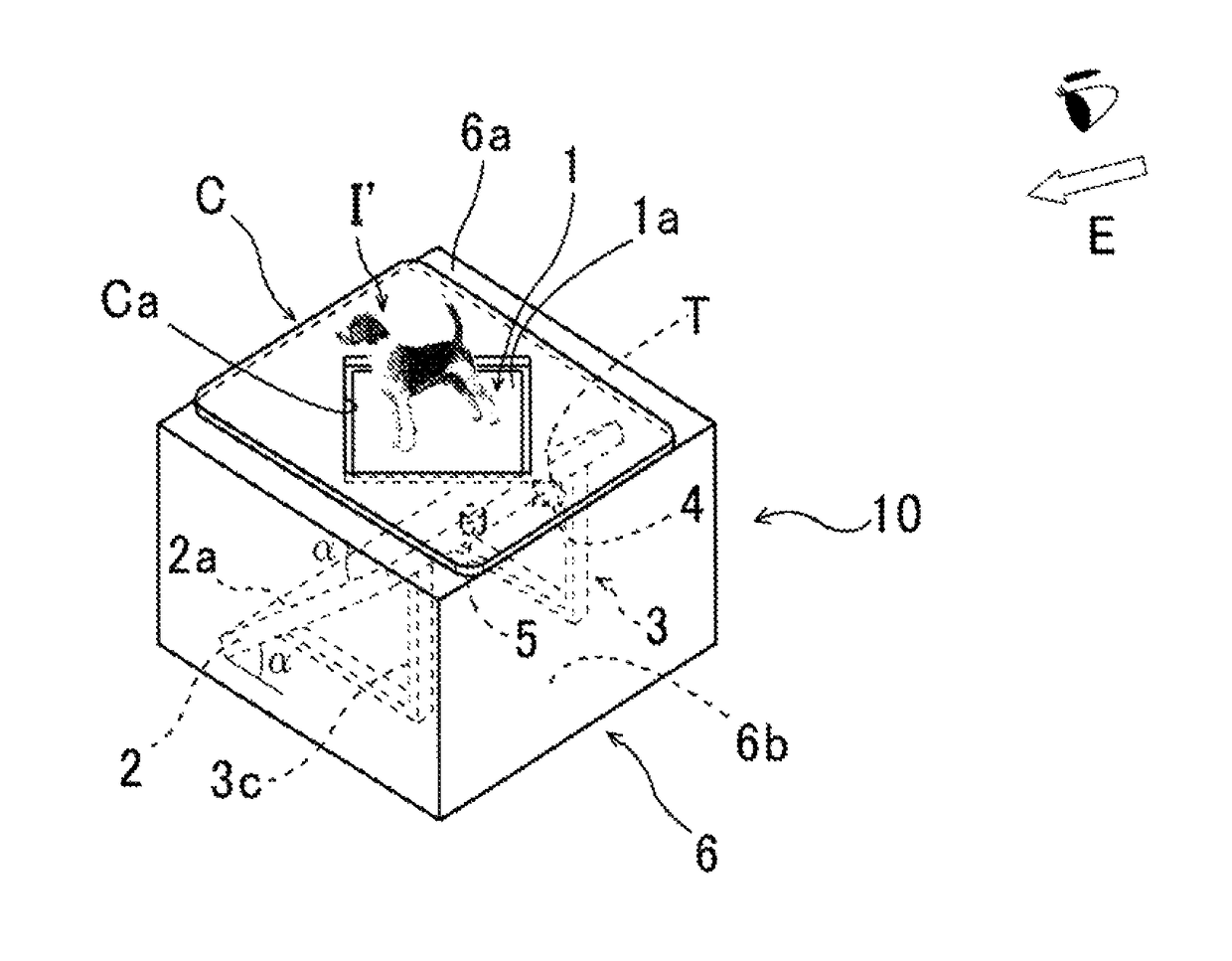
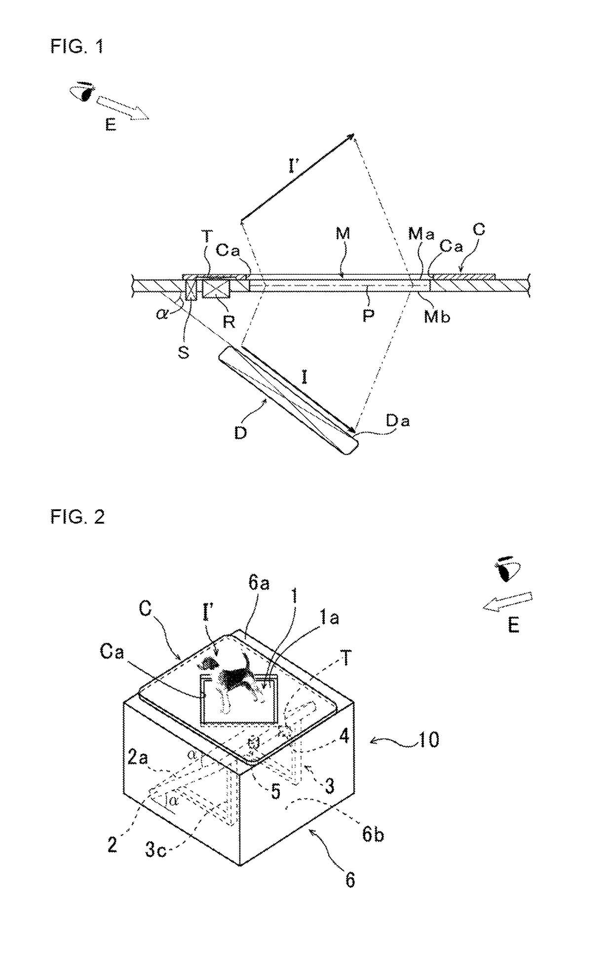
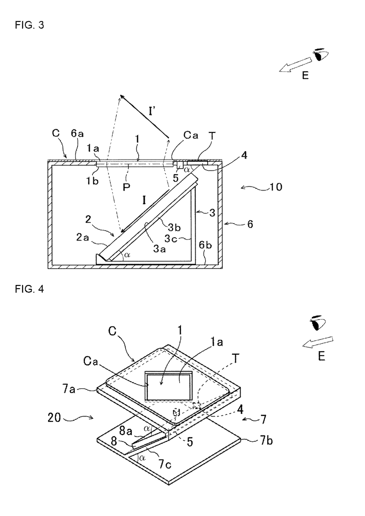
[0048]FIG. 2 is an external perspective view of the display device according to the first embodiment of the present invention. FIG. 3 is a partial sectional view showing the configuration of the display device.

[0049]A display device 10 according to the first embodiment also includes a panel-shaped micromirror array image-forming optical element (micromirror array 1), and a flat panel display (liquid crystal display 2). By using the reflection of light from a large number of micromirrors (corner reflectors) provided in the micromirror array 1, a video picture (image I) displayed on the liquid crystal display 2 disposed on the lower surface 1b side of the micromirror array 1 is image-formed as a spatial image I′ standing up obliquely in space on the upper surface 1a side of the micromirror array 1 in a manner floating up in space. In the display device 10, the liquid crystal display 2 is also placed on a mount...

second embodiment

[0060]As shown in FIG. 4, the housing 7 used in a display device 20 is configured to have no lateral wall surfaces, and has a side surface formed on a bottom plate (sloping surface 7c) used as a mounting surface (mounting surface inclined at the predetermined angle α) for a display (smartphone 8) to be described later. Also, the card C similar to that of the aforementioned embodiment is placed on an upper surface (top plate) 7a of the housing 7.

[0061]An adhesive tape or the like for fixing the display (smartphone 8) is affixed to the mounting surface (sloping surface 7c) of the display device 20, and the smartphone 8 temporarily fixed thereon is removable therefrom. Thus, normally exposed (uncovered) type display parts of tablet PCs, digital photo frames, portable game machines, portable book readers, PDAs, electronic dictionaries and the like which are sized to be placeable on the mounting surface (sloping surface 7c) in addition to the smartphone 8 may be used as the display acco...


PUM


Abstract

A display device includes: an image-forming optical element provided in light-transmissive fashion in an upper surface of an enclosure; a display dispose in an attitude inclined at a predetermined inclination angle with respect to a lower surface of the image-forming optical element; a reader for reading information held by an information holding element in a non-contacting manner; a sensor for sensing whether an object is present on the upper surface of the enclosure or not; and a controller which controls display on the display. The controller prepares an image corresponding to the information holding element, based on the information held therein and transmitted from the reader. The controller causes the prepared image to be displayed as a spatial image at an appropriate moment, based on an object detection signal transmitted from the sensor.

Description

TECHNICAL FIELD[0001]The present invention relates to a display device capable of recognizing an object (information holding element) placed on an upper surface of an enclosure for housing a display to project a two-dimensional video picture appearing three-dimensional and corresponding to this information holding element in space over the device.BACKGROUND ART[0002]Heretofore, there has been known an image display device which includes: an image display surface (liquid crystal display panel and the like) for displaying an image including a three-dimensional image; and an image transmission panel (image-forming optical element) provided on the near side (viewer side) of the image display surface in spaced apart relation to the display surface and for forming the aforementioned image in space (see PTL 1, for example).[0003]On the other hand, the present applicant has already proposed a display device in JP-A-2014-115606, PTL 2 and the like. This display device includes a case for hou...

Claims


Application Information

Patent Timeline
Patent Type & Authority Patents(United States)
IPC IPC(8): H04N13/04G02B27/22H04N13/00H04N13/02G02B5/18G02B27/02G02B5/122H04N13/122
CPCH04N13/0488G02B5/1814G02B27/021G02B27/026G02B27/028G02B27/2292H04N13/0018H04N13/02H04N13/04H04N13/0497G02B5/122G02B2005/1804G02B30/56H04N13/122H04N13/388H04N13/398
Inventor JUNI, NORIYUKI
Owner NITTO DENKO CORP
Why Eureka
Try Eureka