
Fluid filtering device

a filter device and fluid technology, applied in the field of filters, can solve the problems of adverse effects on filtering efficiency and the same problems of liquid filtering devices, and achieve the effect of reducing danger and maintaining filtering efficiency

Active Publication Date: 2017-06-27
BRISK PRECISION INC
View PDF4 Cites 0 Cited by
  • Summary
  • Abstract
  • Description
  • Claims
  • Application Information

AI Technical Summary

Benefits of technology

[0009]The primary objective of the present invention is to provide a fluid filtering device, with which, the pressure difference between input and output pressure can be checked readily, so as to maintain the filtering efficiency while reducing the risk of danger.
[0010]Another objective of the present invention is to provide a fluid filtering device, wherein most of the components are disposed in the casing, which reduces the risk of collision caused damage to the components of the filter.

Problems solved by technology

During the filtering process, the air input and air output must be maintained within a certain level, otherwise, the filtering efficiency will be adversely affected, and the danger might occur if the pressure difference between the air input and output is overly large.
A liquid filtering device also suffers from the same problems that are mentioned above as the air filtering device.

Method used


Image

  • Fluid filtering device
  • Fluid filtering device
  • Fluid filtering device

Examples


first embodiment

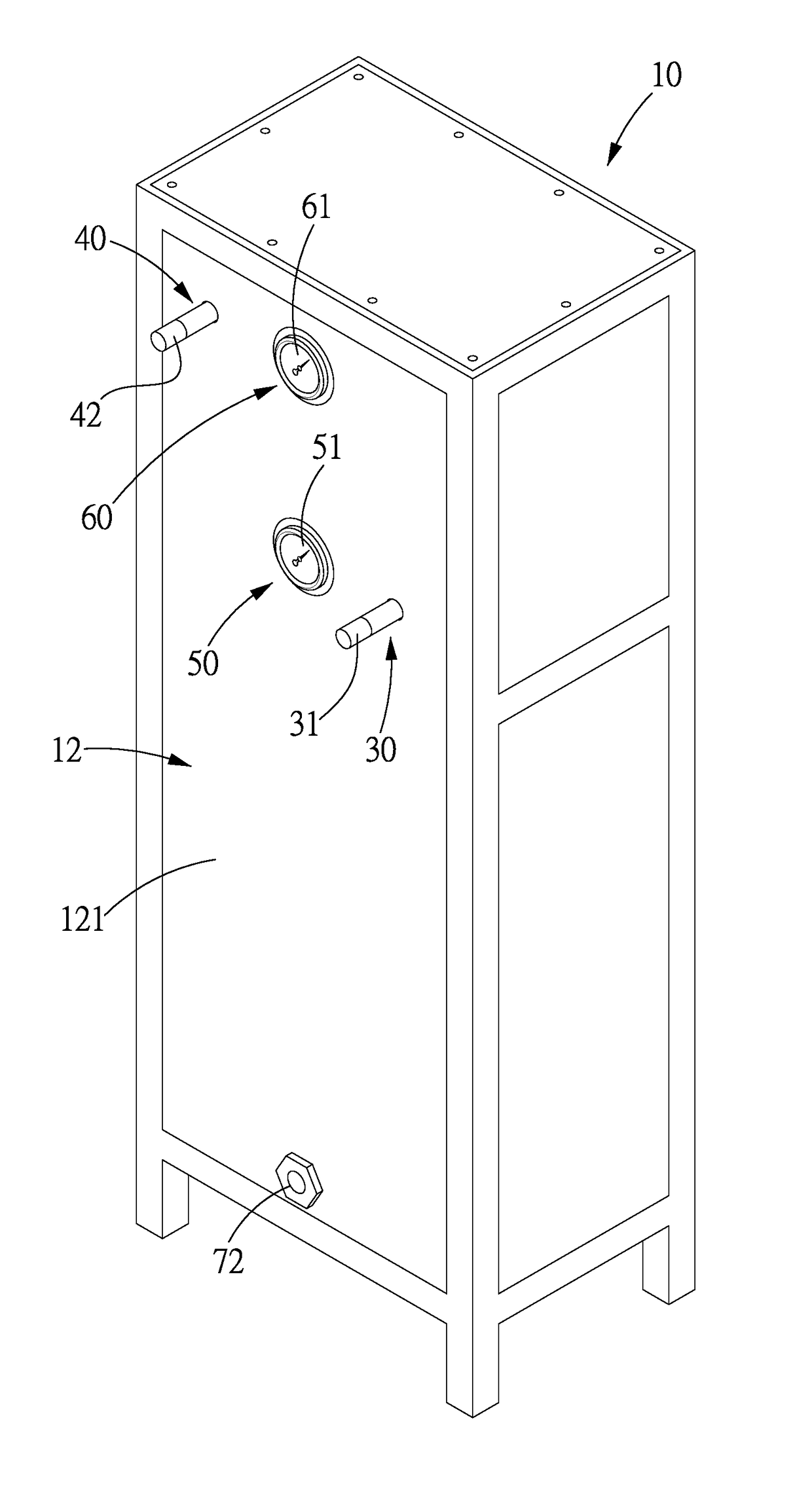
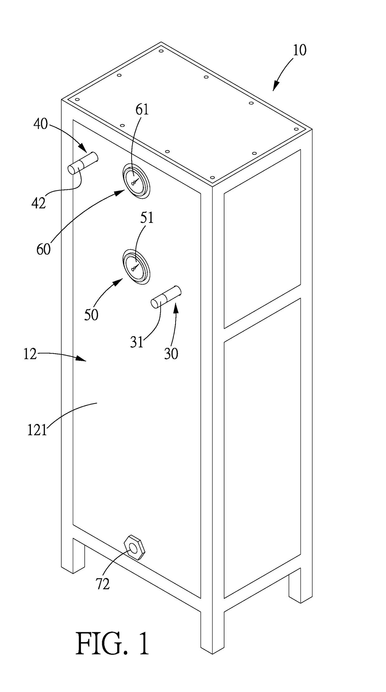
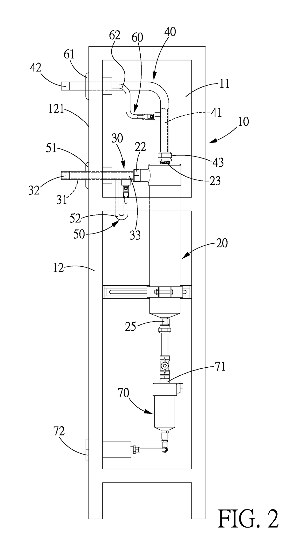
[0029]Referring to FIGS. 1-3, a fluid filtering device in accordance with the present invention comprises: a casing 10, a fluid filter 20, an input pipe 30, an output pipe 40, an input pressure gauge 50, an output pressure gauge 60, and an automated fluid drain controller 70.

[0030]The casing 10 includes a chamber 11. In this embodiment, the chamber 11 is a closed space defined by a plurality of plates 12.

[0031]The fluid filter 20 is disposed in the chamber 11 of the casing 10 and includes a filter space 21, an input hole 22 in communication with the filter space 21, and an output hole 23 in communication with the filter space 21, a filter assembly 24 disposed in the filter space 21 and connected to the output hole 23, and a discharge hole 25 in communication with the filter space 21. In this embodiment, the filter assembly 24 includes plural filter units 241 which are connected to one another in series, and is capable of filtering without power supply. Since the fluid filter 20 is a...

second embodiment

[0046]The second embodiment further offers the advantages as follows:

[0047]First of all, larger filtering capacity: in the casing 10 are disposed the input and output pipes 30, 40, and the four fluid filters 20 which are connected in parallel are disposed between the input and output pipes 30, 40, such arrangements increase filtering capacity, namely, more fluid can be filtered within a given time period. Therefore, the fluid filtering device in accordance with the present invention is capable of filtering fluid at large flow rate. For example, the fluid filtering device can be used to filter the air pollutants from incinerator emission, or cement plant or sand and gravel factory. The fluid filtering device can also be used for small amount fluid filtering, such as the gas for milk products manufacturing, brewing, package and instrument control, semiconductor electronics manufacturing, and medical gas. Besides, the fluid filtering device of the present invention can also be used for...


PUM

PropertyMeasurementUnit
pressureaaaaaaaaaa
sizeaaaaaaaaaa
velocityaaaaaaaaaa

Abstract

A fluid filtering device includes a casing, a fluid filter, an input pipe, an output pipe, an input pressure gauge, an output pressure gauge, and an automated fluid drain controller. The outer input and output ends of the input and output pipes, and the control output end of the automated fluid drain controller are located outside the outer surface of the plates, and the input and output gauge heads are mounted at the outer surface of the plates. By such arrangements, the pressure difference between input and output pressure can be checked readily, so as to maintain the filtering efficiency while reducing the risk of danger.

Description

BACKGROUND OF THE INVENTION[0001]Field of the Invention[0002]The present invention relates to a filter, and more particularly to a fluid filtering device.[0003]Description of the Prior Art[0004]A fluid filtering device is used to remove micro particles, oil and moisture substances from the gas, or to remove the impurities from the liquid.[0005]For example, an air filter for air compressor system (such as the gas for milk products manufacturing, brewing, package and instrument control, semiconductor electronics manufacturing, and medical gas) comprises an air sucking apparatus, a filter connected to the air suck apparatus to filter solid impurities, oil or moisture substances from the air, and an automated drain controller connected to the filter to store or discharge liquid.[0006]Generally, the filtering capacity is decided by the size of the filter, such as 200 ml, 600 ml, 1200 ml, 2000 ml, 3000 ml, etc. During the filtering process, the air input and air output must be maintained ...

Claims


Application Information

Patent Timeline
Patent Type & Authority Patents(United States)
IPC IPC(8): B01D46/44B01D29/94B01D46/00
CPCB01D46/446B01D46/0023B01D46/0039B01D46/62
Inventor CHEN, PO-HUI
Owner BRISK PRECISION INC
Learn More